DTC    P0A94-587    DC / DC Converter Performance

for Preparation Click here


DESCRIPTION

Refer to the description of the boost converter. (Click here)
The MG ECU uses a voltage sensor that is built into the boost converter to detect the high voltage (VL) before it is boosted. The ECU also uses a battery smart unit to detect HV battery voltage (VB).

DTC No.
INF Code
DTC Detection Condition
Trouble Area
P0A94
587
Voltages from HV battery voltage (VB) sensor and boost converter voltage (VL) sensor deviate
  1. w/ converter inverter assembly (MG ECU)
  2. Battery smart unit

MONITOR DESCRIPTION

The HV control ECU monitors signals of HV battery voltage (VB) and boost converter voltage (VL) sensors. When a large difference occurs between the voltages from the VB and VL sensors, the HV control ECU interprets this as a failure of either of the sensors. The HV control ECU then illuminates the MIL and sets a DTC.

INSPECTION PROCEDURE

CAUTION:
  1. Before inspecting the high-voltage system, take safety precautions to prevent electrical shocks, such as wearing insulated gloves and removing the service plug grip. After removing the service plug grip, put it in your pocket to prevent other technicians from reconnecting it while you are working on the high-voltage system.
  2. After disconnecting the service plug grip, wait for at least 5 minutes before touching any of the high-voltage connectors or terminals.

HINT:
At least 5 minutes is required to discharge the high-voltage capacitor inside the w/ converter inverter assembly.

1.READ OUTPUT DTC (HV)
  1. Connect the intelligent tester to the DLC3.

  1. Turn the ignition switch to the ON position.

  1. Select the following menu items: Powertrain / Hybrid Control / DTC.

  1. Read output DTC. (Click here)


Result:
The DTCs shown in the table below are output:

Output DTC
Proceed to
DTCs P0A94-587 and P0A1F-129 (HV battery voltage circuit malfunction)
A
DTCs P0A94-587 and P0A94-442 (Abnormal voltage execution value)
B
DTCs P0A94-587 and P0A94-585 (Boost converter voltage (VL) sensor performance problem)
C
DTC P0A94-587 only, or DTCs other than above
D


A
GO TO DTC P0A1F-129

B
REPLACE W/ CONVERTER INVERTER ASSEMBLY

C
GO TO DTC P0A94-585
D


2.READ OUTPUT DTC (HV)
  1. Connect the intelligent tester to the DLC3.

  1. Put the vehicle into the READY-on state and move the shift lever to the N position.

  1. Turn the A/C switch to the MAX COOL position.

  1. Select the following menu items: Powertrain / Hybrid Control / Data List / Pwr Resource IB.

  1. Confirm that the Pwr Resource IB is more than 3 A.

  1. Leave the vehicle in the above condition for 15 seconds.

    NOTICE:
    If the low battery charge warning light comes on, move the shift lever to the P position and start the engine to charge the HV battery. After turning the engine off, perform step 2 again.

  1. Select the following menu items: Powertrain / Hybrid Control / DTC.

  1. Read output DTC. (Click here)

    Result:
    The DTCs shown in the table below are output:

    DTC No.
    Relevant Diagnosis
    Proceed to
    P0A1F-129
    HV battery voltage circuit malfunction
    A
    P0A94-585
    Boost converter voltage (VL) sensor performance problem
    B
    P3000-388
    Discharge inhibition
    C
    P3004-132
    High voltage power supply line problem
    D
    No DTC is output.
    -
    E


A
REPLACE BATTERY SMART UNIT

B
REPLACE W/ CONVERTER INVERTER ASSEMBLY

C
LEAVE SHIFT LEVER IN P POSITION, AND CHARGE HV BATTERY IN IDLE STATUS UNTIL IDLING STOP

D
REPLACE BATTERY SMART UNIT
E


3.READ OUTPUT DTC (HV)
  1. Connect the intelligent tester to the DLC3.

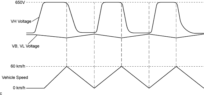
  1. Select the following menu items: Powertrain / Hybrid Control / Data List / Pwr Resource VB, VL and VH.

  1. Test-drive the vehicle while monitoring the HV battery, pre-boost, and post-boost voltages in the ECU data list.

    HINT:
    Repeat full acceleration to 60 km/h and then full braking to a complete stop several times.

  1. Check for DTCs and check the result of monitoring the data list.

    Result:
    The DTCs shown in the table below are output:

    DTC No.
    Relevant Diagnosis
    Proceed to
    P0A1F-129
    HV battery voltage circuit malfunction
    A
    P0A94-585
    Boost converter voltage (VL) sensor performance problem
    B
    P3000-388
    Discharge inhibition
    C
    P3004-132
    High voltage power supply line problem
    D
    Result of monitoring the ECU data list:

    ECU Data List
    Result:
    Proceed to
    VB
    Deviates from the data behavior shown below
    A
    VL
    Deviates from the data behavior shown below
    B

HINT:
If no DTC is output and the reading on the ECU data list is normal, proceed to E.


A105189E01


A
REPLACE BATTERY SMART UNIT

B
REPLACE W/ CONVERTER INVERTER ASSEMBLY

C
LEAVE SHIFT LEVER IN P POSITION, AND CHARGE HV BATTERY IN IDLE STATUS UNTIL IDLING STOP

D
REPLACE BATTERY SMART UNIT
E

REPLACE BATTERY SMART UNIT AND W/ CONVERTER INVERTER ASSEMBLY