DTC
C1235/35 Foreign Object is Attached on Tip of Front Speed Sensor RH |  |
DTC
C1236/36 Foreign Object is Attached on Tip of Front Speed Sensor LH |
DTC
C1238/38 Foreign Object is Attached on Tip of Rear Speed Sensor RH |
DTC
C1239/39 Foreign Object is Attached on Tip of Rear Speed Sensor LH |
DTC
C1275/75 Abnormal Change in Output Signal of Front Speed Sensor RH (Test Mode DTC) |
DTC
C1276/76 Abnormal Change in Output Signal of Front Speed Sensor LH (Test Mode DTC) |
DTC
C1277/77 Abnormal Change in Output Signal of Rear Speed Sensor RH (Test Mode DTC) |
DTC
C1278/78 Abnormal Change in Output Signal of Rear Speed Sensor LH (Test Mode DTC) |
DTC No.
| INF Code
| DTC Detecting Condition
| Trouble Area
|
C1235/35
| 302
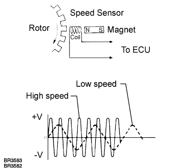
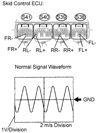
| Pulse waveform of speed sensor signal is abnormal for at least 5 sec. when vehicle speed is 12 mph (20 km/h) or more.
| - Right front speed sensor
- Each speed sensor circuit
- Sensor installation
- Speed sensor rotor
- Skid control ECU
|
C1236/36
| 303
| Pulse waveform of speed sensor signal is abnormal for at least 5 sec. when vehicle speed is 12 mph (20 km/h) or more.
| - Left front speed sensor
- Each speed sensor circuit
- Sensor installation
- Speed sensor rotor
- Skid control ECU
|
C1238/38
| 304
| Pulse waveform of speed sensor signal is abnormal for at least 5 sec. when vehicle speed is 12 mph (20 km/h) or more.
| - Right rear speed sensor
- Each speed sensor circuit
- Sensor installation
- Speed sensor rotor
- Skid control ECU
|
C1239/39
| 305
| Pulse waveform of speed sensor signal is abnormal for at least 5 sec. when vehicle speed is 12 mph (20 km/h) or more.
| - Left rear speed sensor
- Each speed sensor circuit
- Sensor installation
- Speed sensor rotor
- Skid control ECU
|