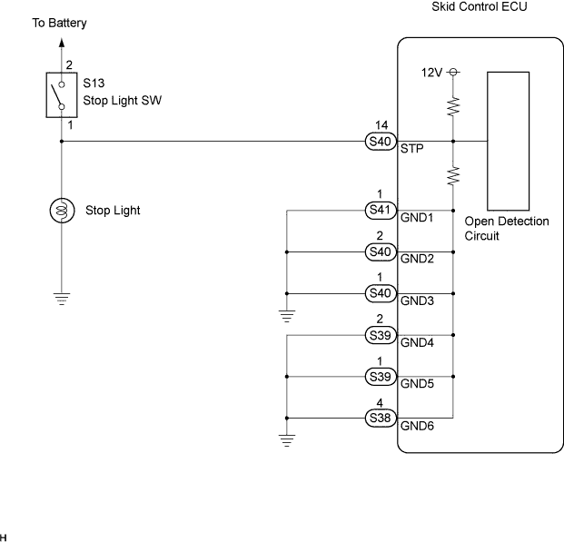
DTC C1249/49 Open in Stop Light Switch Circuit |
| DTC No. | INF Code | DTC Detecting Condition | Trouble Area |
| C1249/49 | 520 | Stop light switch circuit is open for at least 10 sec. when IG1 terminal voltage is between 9.5 V and 17.2 V |
|
| 1.CHECK STOP LIGHT SWITCH OPERATION |
Check that the stop light comes on when the brake pedal is depressed and turns off when the brake pedal is released.
| Condition | Illumination Condition |
| Brake pedal depressed | ON |
| Brake pedal released | OFF |
|
| ||||
| OK | |
| 2.CHECK HARNESS AND CONNECTOR (BETWEEN SKID CONTROL ECU AND STOP LIGHT SWITCH) |
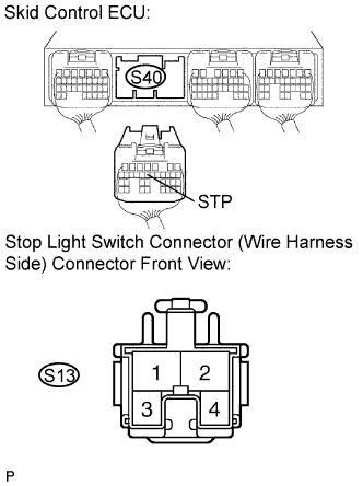 |
Disconnect the stop light switch connector and skid control ECU connector.
Measure the resistance according to the value(s) in the table below.
| Tester Connection | Specified Condition |
| S40-14 (STP) - S13-1 | Below 1 Ω |
|
| ||||
| OK | |
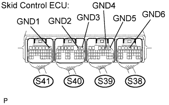
| 3.INSPECT SKID CONTROL ECU (GND TERMINAL) |
 |
Connect the skid control ECU connector.
Measure the resistance according to the value(s) in the table below.
| Tester Connection | Specified Condition |
| S41-1 (GND1) - Body ground | Below 1 Ω |
| S40-2 (GND2) - Body ground | Below 1 Ω |
| S40-1 (GND3) - Body ground | Below 1 Ω |
| S39-2 (GND4) - Body ground | Below 1 Ω |
| S39-1 (GND5) - Body ground | Below 1 Ω |
| S38-4 (GND6) - Body ground | Below 1 Ω |
|
| ||||
| OK | |
| 4.INSPECT STOP LIGHT SWITCH ASSEMBLY |
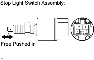 |
Disconnect the stop light switch assembly connector.
Measure the resistance according to the value(s) in the table below.
| Switch Condition | Tester Connection | Specified Condition |
| Switch pin free | 1 - 2 | Below 1 Ω |
| Switch pin pushed in | 1 - 2 | 10 kΩ or higher |
|
| ||||
| OK | |
| 5.RECONFIRM DTC |
Clear the DTC (Click here).
Turn the ignition switch on.
Depress the brake pedal several times to test the stop light circuit.
Check that the same DTC is recorded (Click here).
| Condition | Proceed To |
| DTC is not output | A |
| DTC is output | B |
|
| ||||
| A | ||
| ||
