ELECTRONICALLY CONTROLLED BRAKE SYSTEM > Brake Warning Light Remains ON |
| 1.CHECK DTC |
Check if the ABS, VSC and/or ECB DTC is output (Click here).
| Condition | Proceed To |
| DTC is not output | A |
| DTC is output | B |
|
| ||||
| A | |
| 2.INSPECT CAN COMMUNICATION SYSTEM |
Check if the CAN communication system DTC is output (Click here for LHD, for Click here RHD).
| Condition | Proceed To |
| DTC is not output | A |
| DTC is output | B |
|
| ||||
| A | |
| 3.INSPECT MULTIPLEX COMMUNICATION SYSTEM |
Check if the multiplex communication system DTC is output (Click here).
| Condition | Proceed To |
| DTC is not output | A |
| DTC is output | B |
|
| ||||
| A | |
| 4.INSPECT IF SKID CONTROL ECU CONNECTOR IS SECURELY CONNECTED |
Check the skid control ECU connector's connection.
|
| ||||
| OK | |
| 5.INSPECT BATTERY |
Check the battery voltage.
|
| ||||
| OK | |
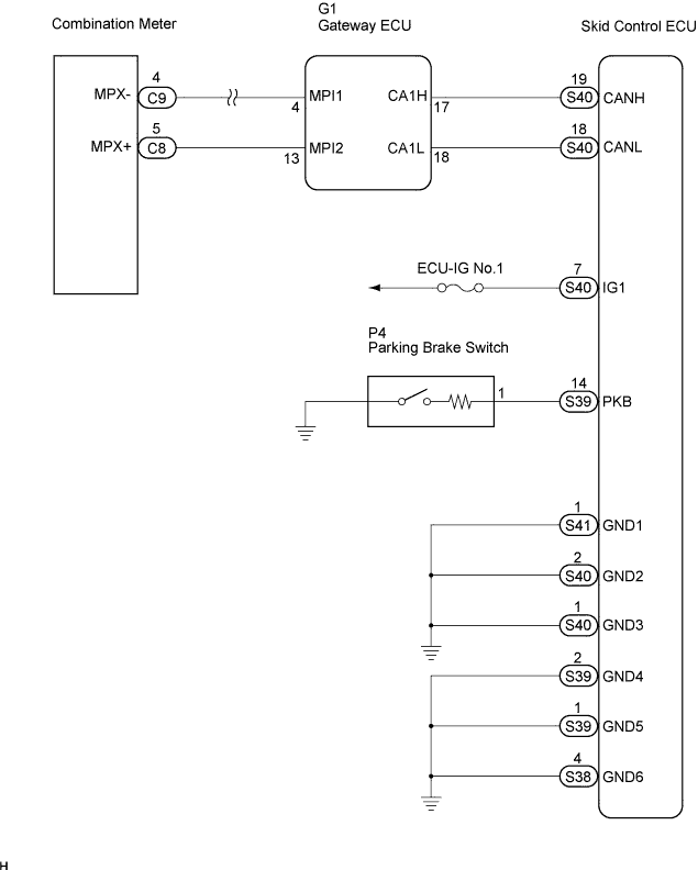
| 6.INSPECT SKID CONTROL ECU (IG1 TERMINAL) |
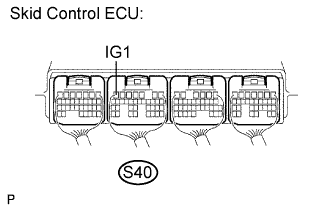 |
Turn the ignition switch on.
Measure the voltage according to the value(s) in the table below.
| Tester Connection | Condition | Specified Condition |
| S40-7 (IG1) - Body ground | Ignition switch on | 10 to 14 V |
|
| ||||
| OK | |
| 7.INSPECT SKID CONTROL ECU (GND TERMINAL) |
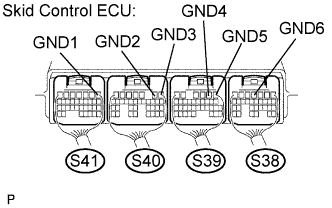 |
Measure the resistance according to the value(s) in the table below.
| Tester Connection | Specified Condition |
| S41-1 (GND1) - Body ground | Below 1 Ω |
| S40-2 (GND2) - Body ground | Below 1 Ω |
| S40-1 (GND3) - Body ground | Below 1 Ω |
| S39-2 (GND4) - Body ground | Below 1 Ω |
| S39-1 (GND5) - Body ground | Below 1 Ω |
| S38-4 (GND6) - Body ground | Below 1 Ω |
|
| ||||
| OK | |
| 8.READ VALUE OF INTELLIGENT TESTER (PARKING BRAKE SWITCH) |
Connect the intelligent tester to the DLC3.
Turn the ignition switch on.
Select the DATA LIST mode on the intelligent tester.
| Item (Display) | Measurement Item/Range (Display) | Normal Condition |
| PARKING BRAKE SW | Parking brake switch/ON or OFF | ON: Parking brake pedal depressed OFF: Parking brake pedal released |
Using the intelligent tester, check the input of switch operation when the parking brake pedal is operated.
|
| ||||
| OK | |
| 9.INSPECT COMBINATION METER ASSEMBLY |
Check the combination meter assembly (Click here).
|
| ||||
| OK | ||
| ||
| 10.INSPECT PARKING BRAKE SWITCH |
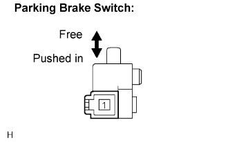 |
Disconnect the parking brake switch connector.
Measure the resistance according to the value(s) in the table below.
| Tester Connection | Condition | Specified Condition |
| 1 - Body ground | Parking brake switch ON (Switch pin free) | Below 1 Ω |
| 1 - Body ground | Parking brake switch OFF (Switch pin pushed in) | 10 kΩ or higher |
|
| ||||
| OK | |
| 11.CHECK HARNESS AND CONNECTOR (BETWEEN PARKING BRAKE SWITCH AND SKID CONTROL ECU) |
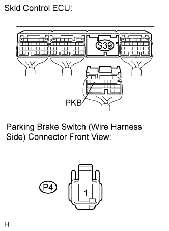 |
Disconnect the skid control ECU connector S39 and parking brake switch connector.
Measure the resistance according to the value(s) in the table below.
| Tester Connection | Specified Condition |
| S39-14 (PKB) - P4-1 | Below 1 Ω |
| S39-14 (PKB) | 10 kΩ or higher |
|
| ||||
| OK | ||
| ||
