COOLING FAN ECU > ON-VEHICLE INSPECTION |
| 1. CHECK COOLING FAN ECU (NO.1,NO.2) |
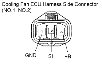 |
Inspect the input voltage.
Disconnect the cooling fan ECU connectors.
Turn the ignition switch on.
Measure the voltage between terminals +B and GND.
Reconnect the connectors.
| Cooling fan operation | Wire harness condition |
| Not in operation | Short |
| In continuous operation | Open |
Check the HV control ECU power source.
Check RFC1 and RFC2 signal generation.
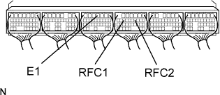 |
Connect an oscilloscope to terminals RFC1 (RFC2) and E1 of the HV control ECU.
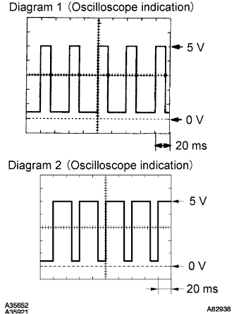 |
Check the signal generation and measure the current according to the value(s) in the table below.
| Condition | RFC1 (RFC2) signal generation | Fan operation | Fan operation |
| Engine stopped, IG switch ON | - | - | Not operate |
| Engine idling, A/C ON | - | - | Not operate |
| Engine idling, A/C ON | See Diagram 1 | 3 to 13 A | Operate |
| Engine idling, engine coolant temperature sensor connector disconnected | See Diagram 2 | 3 to 21 A | Operate (High speed) |
