DTC C1528 Motor Rotation Angle Sensor Malfunction |
| DTC No. | DTC Detection Item | Trouble Area |
| C1528 | Motor rotation angle sensor malfunction (e.g. An open, short to ground, or short to B+ in the rotation angle sensor circuit) |
|
| 1.CHECK POWER STEERING EARTH WIRE (BETWEEN POWER STEERING LINK ASSEMBLY AND BODY GROUND) |
Check the installation condition of the power steering earth wire connected to the power steering link assembly.
|
| ||||
| OK | |
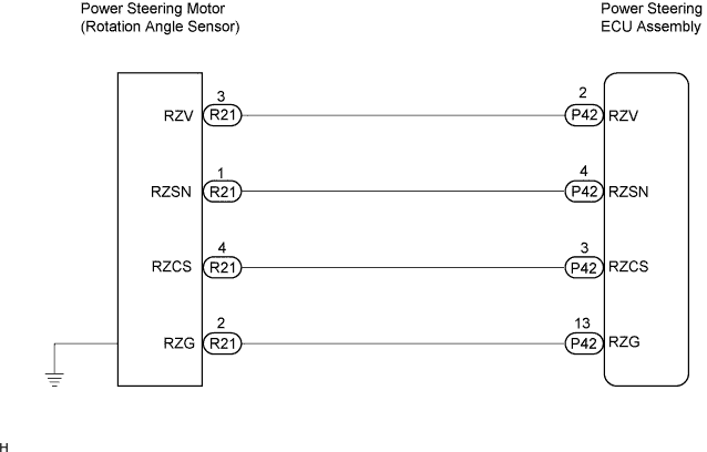
| 2.CHECK HARNESS AND CONNECTOR (BETWEEN ECU ASSEMBLY AND MOTOR ROTATION ANGLE SENSOR) |
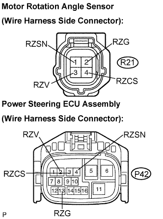 |
Disconnect the R21 connector from the power steering link assembly.
Disconnect the P42 connector from the power steering ECU assembly.
Measure the resistance according to the value(s) in the table below.
| Tester connection (Symbols) | Condition | Specified condition |
| R21-1 (RZSN) - P42-4 (RZSN) | Always | Below 1 Ω |
| R21-2 (RZG) - P42-13 (RZG) | Always | Below 1 Ω |
| R21-3 (RZV) - P42-2 (RZV) | Always | Below 1 Ω |
| R21-4 (RZCS) - P42-3 (RZCS) | Always | Below 1 Ω |
| R21-1 (RZSN) - Body ground | Always | 10 kΩ or higher |
| R21-2 (RZG) - Body ground | Always | 10 kΩ or higher |
| R21-3 (RZV) - Body ground | Always | 10 kΩ or higher |
| R21-4 (RZCS) - Body ground | Always | 10 kΩ or higher |
|
| ||||
| OK | |
| 3.INSPECT POWER STEERING LINK ASSEMBLY (MOTOR ROTATION ANGLE SENSOR) |
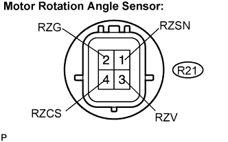 |
Measure the resistance according to the value(s) in the table below.
| Tester connection (Symbols) | Condition | Specified condition |
| R21-1 (RZSN) - R21-2 (RZG) | Always | 50 to 140 Ω |
| R21-3 (RZV) - R21-2 (RZG) | Always | 50 to 140 Ω |
| R21-4 (RZCS) - R21-2 (RZG) | Always | 15 to 45 Ω |
|
| ||||
| OK | |
| 4.REPLACE POWER STEERING ECU ASSEMBLY |
Replace the power steering ECU assembly (Click here).
| NEXT | |
| 5.INITIALIZE ROTATION ANGLE SENSOR VALUE AND CALIBRATE TORQUE SENSOR ZERO POINT |
Initialize the rotation angle sensor value and calibrate the torque sensor zero point (Click here).
| NEXT | |
| 6.RECONFIRM DTC |
Check for DTCs (Click here).
Is DTC C1528 output?
|
| ||||
| OK | ||
| ||
