DTC No.
| INF Code
| DTC Detecting Condition
| Trouble Area
|
C1247/47
| 171
| Sensor power source voltage (VCSK) is 3.6 V or less or 4.95 V or more for at least 1.2 sec.
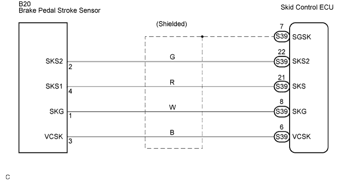
| - Brake pedal stroke sensor
- Brake pedal stroke sensor circuit
- Brake pedal stroke sensor power supply
- Skid control ECU
|
C1247/47
| 172
| Ratio of sensor output voltage 1 (SKS1) to sensor power source voltage (VCSK) is less than 3% or 97% or more for at least 1.2 sec.
| - Brake pedal stroke sensor
- Brake pedal stroke sensor circuit
|
C1247/47
| 173
| Ratio of sensor output voltage 2 (SKS2) to sensor power source voltage (VCSK) is less than 3% or 97% or more for at least 1.2 sec.
| - Brake pedal stroke sensor
- Brake pedal stroke sensor circuit
|
C1247/47
| 174
| Sensor output 1 (SKS1) calculation value becomes 20 mm or more for at least 1.2 sec. at an interval of 0.006 sec. (changes due to interference).
| - Brake pedal stroke sensor
- Brake pedal stroke sensor circuit
|
C1247/47
| 175
| Sensor output 2 (SKS2) calculation value becomes 20 mm or more for at least 1.2 sec. at an interval of 0.006 sec. (changes due to interference).
| - Brake pedal stroke sensor
- Brake pedal stroke sensor circuit
|
C1247/47
| 176
| Zero point stored value (ratio to power source voltage) of sensor output 1 (SKS1) is 0.46 or more or 0.03 or less.
| - Brake pedal stroke sensor
- Brake pedal stroke sensor circuit
- Sensor installation
|
C1247/47
| 177
| Zero point stored value (ratio to power source voltage) of sensor output 2 (SKS2) is 0.97 or more or 0.48 or less.
| - Brake pedal stroke sensor
- Brake pedal stroke sensor circuit
|
C1247/47
| 179
| - Sum of SKS1/VSCK and SKS2/VSCK is 1.155 or more or 0.845 or less for at least 1 sec.
- Difference between sensor output 1 (SKS1) and sensor output 2 (SKS2) is excessively large for at least 0.2 sec.
| - Brake pedal stroke sensor
- Brake pedal stroke sensor circuit
|
C1247/47
| 180
| - Difference between zero point output value and stored value is 0.5 or more for at least 0.05 sec.
- Short between SKS1 and SKS2 output line.
| - Brake pedal stroke sensor
- Brake pedal stroke sensor circuit
- Skid control ECU
|
C1392/48
| 178
| Zero point calibration of stroke sensor is unfinished.
| - Brake pedal stroke sensor zero point calibration undone (initialization of linear solenoid valve and calibration undone)
- Skid control ECU
|