DTC C1311/11 Open in Main Relay 1 Circuit |
DTC C1312/12 Short in Main Relay 1 Circuit |
DTC C1313/13 Open in Main Relay 2 Circuit |
DTC C1314/14 Short in Main Relay 2 Circuit |
| DTC No. | INF Code | DTC Detecting Condition | Trouble Area |
| C1311/11 | 1 |
|
|
| C1312/12 | 3 | Relay contact is on for at least 4 sec. when main relay 1 is off. |
|
| C1313/13 | 4 |
|
|
| C1314/14 | 6 | Relay contact is on for at least 4 sec. when main relay 2 is off. |
|
| 1.PERFORM ACTIVE TEST BY INTELLIGENT TESTER (ABS NO.1 RELAY, ABS NO.2 RELAY) |
Connect the intelligent tester to the DLC3.
Turn the ignition switch on.
Select the ACTIVE TEST mode on the intelligent tester.
Check the operation sound of the ABS No.1 and No.2 relays.
| Item | Vehicle Condition / Test Details | Diagnostic Note |
| ECB Main Relay | Turns ABS No.1 relay ON/OFF | Operating of solenoid (clicking sound) can be heard |
| ECB Main Relay 2 | Turns ABS No.2 relay ON/OFF | Operating of solenoid (clicking sound) can be heard |
|
| ||||
| OK | |
| 2.INSPECT ABS MAIN RELAY (ABS NO.1 RELAY, ABS NO.2 RELAY) |
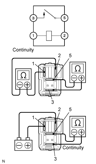 |
Remove the ABS No.1 relay and ABS No.2 relay.
Measure the resistance according to the value(s) in the table below.
| Tester Connection | Specified Condition |
| Terminal 1 - Terminal 2 | 100 Ω |
| Terminal 3 - Terminal 5 | 10 kΩ or higher (No Continuity) |
Apply battery voltage between terminals 1 and 2.
Measure the resistance according to the value(s) in the table below.
| Tester Connection | Specified Condition |
| Terminal 3 - Terminal 5 | Below 1 Ω |
|
| ||||
| OK | |
| 3.INSPECT FUSE (ABS NO.1, ABS NO.2 AND ABS NO.3 FUSES) |
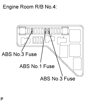 |
Remove the ABS No.1, ABS No.2 and ABS No.3 fuses.
Measure the resistance according to the value(s) in the table below.
| Fuse | Specified Condition |
| ABS No.1 Fuse | Below 1 Ω (Continuity) |
| ABS No.2 Fuse | Below 1 Ω (Continuity) |
| ABS No.3 Fuse | Below 1 Ω (Continuity) |
|
| ||||
| OK | |
| 4.INSPECT SKID CONTROL ECU (+BI1, +BI2 TERMINAL) |
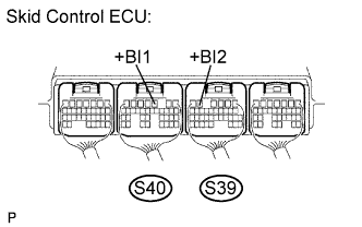 |
Measure the voltage according to the value(s) in the table below.
| Tester Connection | Specified Condition |
| S40-3 (+BI1) - Body ground | 10 to 14 V |
| S39-5 (+BI2) - Body ground | 10 to 14 V |
|
| ||||
| OK | |
| 5.INSPECT SKID CONTROL ECU (+BO1, +BO2, R1+, R2+ TERMINAL) |
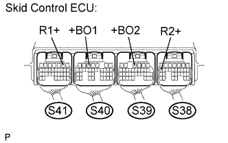 |
Measure the voltage according to the value(s) in the table below.
| Tester Connection | Specified Condition |
| S41-2 (R1+) - Body ground | 10 to 14 V |
| S40-5 (+BO1) - Body ground | 10 to 14 V |
| S39-4 (+BO2) - Body ground | 10 to 14 V |
| S38-17 (R2+) - Body ground | 10 to 14 V |
|
| ||||
| OK | |
| 6.INSPECT SKID CONTROL ECU (BS1, BS2 TERMINAL) |
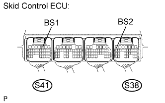 |
Measure the voltage according to the value(s) in the table below.
| Tester Connection | Specified Condition |
| S41-3 (BS1) - Body ground | 10 to 14 V |
| S38-7 (BS2) - Body ground | 10 to 14 V |
|
| ||||
| OK | ||
| ||
