DTC C1315/31 SMC1 Changeover Solenoid Malfunction |
DTC C1316/32 SMC2 Changeover Solenoid Malfunction |
DTC C1352/21 Front Increasing Pressure Solenoid RH Malfunction |
DTC C1353/23 Front Increasing Pressure Solenoid LH Malfunction |
DTC C1354/25 Rear Increasing Pressure Solenoid RH Malfunction |
DTC C1355/27 Rear Increasing Pressure Solenoid LH Malfunction |
DTC C1356/22 Front Decreasing Pressure Solenoid RH Malfunction |
DTC C1357/24 Front Decreasing Pressure Solenoid LH Malfunction |
DTC C1358/26 Rear Decreasing Pressure Solenoid RH Malfunction |
DTC C1359/28 Rear Decreasing Pressure Solenoid LH Malfunction |
| DTC No. | INF Code | DTC Detecting Condition | Trouble Area |
| C1315/31 | 61 |
|
|
| C1315/31 | 62 | Open circuit in SMC1 continues for 0.05 sec. or more when SMC1 is off |
|
| C1315/31 | 63 | Open circuit in SMC1 continues for 0.05 sec. or more when SMC1 is off |
|
| C1315/31 | 64 | Over current in SMC1 continues for 0.05 sec. or more. |
|
| C1316/32 | 66 |
|
|
| C1316/32 | 67 | Open circuit in SMC2 continues for 0.05 sec. or more when SMC2 is off. |
|
| C1316/32 | 68 | Open circuit in SMC2 continues for 0.05 sec. or more. |
|
| C1316/32 | 69 | Open circuit in SMC2 continues for 0.05 sec. or more. |
|
| C1352/21 | 11 | Open circuit in SLAFR continues for 0.05 sec. or more when SLAFR is off. |
|
| C1352/21 | 12 | Open circuit in SLAFR continues for 0.05 sec. or more when SLAFR is on. |
|
| C1352/21 | 13 | Short to +B or voltage leak in SLAFR continues for 0.05 sec. or more. |
|
| C1352/21 | 14 | Over current in SLAFR continues for 0.05 sec. or more |
|
| C1353/23 | 21 | Open circuit in SLAFL continues for 0.05 sec. or more when SLAFL is off. |
|
| C1353/23 | 22 | Open circuit in SLAFL continues for 0.05 sec. or more when SLAFL is on. |
|
| C1353/23 | 23 | Short to +B or voltage leak in SLAFL continues for 0.05 sec. or more. |
|
| C1353/23 | 24 | Over current in SLAFL continues for 0.05 sec. or more. |
|
| C1354/25 | 31 | Open circuit in SLARR continues for 0.05 sec. or more when SLARR is off |
|
| C1354/25 | 32 | Open circuit in SLARR continues for 0.05 sec. or more when SLARR is on. |
|
| C1354/25 | 33 | Short to +B or voltage leak in SLARR continues for 0.05 sec. or more. |
|
| C1354/25 | 34 | Over current in SLARR continues for 0.05 sec. or more. |
|
| C1355/27 | 41 | Open circuit in SLARL continues for 0.05 sec. or more when SLARL is off. |
|
| C1355/27 | 42 | Open circuit in SLARL continues for 0.05 sec. or more when SLARL is on. |
|
| C1355/27 | 43 | Short to +B or voltage leak in SLARL continues for 0.05 sec. or more. |
|
| C1355/27 | 44 | Over current in SLARL continues for 0.05 sec. or more. |
|
| C1356/22 | 16 | Open circuit in SLRFR continues for 0.05 sec. or more when SLRFR is off. |
|
| C1356/22 | 17 | Open circuit in SLRFR continues for 0.05 sec. or more when SKRFR is on. |
|
| C1356/22 | 18 | Short to +B or voltage leak in SLRFR continues for 0.05 sec. or more. |
|
| C1356/22 | 19 | Over current in SLRFR continues for 0.05 sec. or more. |
|
| C1357/24 | 26 | Open circuit in SLRFL continues or 0.05 sec. or more when SLRFL is off. |
|
| C1357/24 | 27 | Open circuit in SLRFL continues for 0.05 sec. or more when SLRFL is on. |
|
| C1357/24 | 28 | Short to +B or voltage leak in SLRFL continues for 0.05 sec. or more. |
|
| C1357/24 | 29 | Over current in SLRFL continues for 0.05 sec. or more. |
|
| C1358/26 | 36 | Open circuit in SLRRR continues for 0.05 sec. or more when SLRRR is off. |
|
| C1358/26 | 37 | Open circuit in SLRRR continues for 0.05 sec. or more when SLRRR is on. |
|
| C1358/26 | 38 | Short to +B or voltage leak in SLRRR continues for 0.05 sec. or more. |
|
| C1358/26 | 39 | Over current in SLRRR continues for 0.05 sec. or more. |
|
| C1359/28 | 46 | Open circuit in SLRRL continues for 0.05 sec. or more when SLRRL is off. |
|
| C1359/28 | 47 | Open circuit in SLRRL continues for 0.05 sec. or more when SLRRL is on. |
|
| C1359/28 | 48 | Short to +B or voltage leak in SLRRL continues for 0.05 sec. or more. |
|
| C1359/28 | 49 | Over current in SLRRL continues for 0.05 sec. or more. |
|
| 1.INSPECT BRAKE ACTUATOR ASSEMBLY |
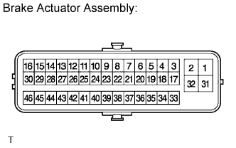 |
Disconnect the brake actuator connector.
Measure the resistance according to the value(s) in the table below.
| Tester Connection | Specified Condition |
| 37 (SMC1) - 36 (BS1) | 15.3 to 17.3 Ω |
| 19 (SMC2) - 20 (BS2) | 15.3 to 17.3 Ω |
| 44 (SLAFR+) - 43 (SLAFR-) | 3.6 to 4.2 Ω |
| 28 (SLRFR+) - 27 (SLRFR-) | 3.6 to 4.2 Ω |
| 35 (SLAFL+) - 38 (SLAFL-) | 3.6 to 4.2 Ω |
| 21 (SLRFL+) - 22 (SLRFL-) | 3.6 to 4.2 Ω |
| 41 (SLARL+) - 42 (SLARL-) | 3.6 to 4.2 Ω |
| 25 (SLRRL+) - 26 (SLRRL-) | 4.4 to 5.0 Ω |
| 39 (SLARR+) - 40 (SLARR-) | 3.6 to 4.2 Ω |
| 23 (SLRRR+) - 24 (SLRRR-) | 4.4 to 5.0 Ω |
|
| ||||
| OK | |
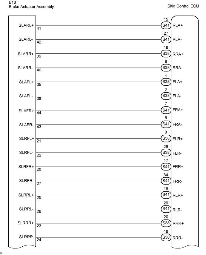
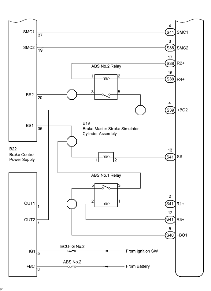
| 2.CHECK HARNESS AND CONNECTOR (BETWEEN BRAKE ACTUATOR ASSEMBLY AND SKID CONTROL ECU) |
Measure the voltage according to the value(s) in the table below.
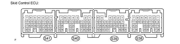
| Tester Connection | Condition | Specified Condition |
| S41-4 (SMC1) - Body ground | Ignition switch ON Brake pedal released | 10 to 14 V |
| S38-3 (SMC2) - Body ground | Ignition switch ON Brake pedal released | 10 to 14 V |
| S41-7 (FRA+) - Body ground | Ignition switch ON Brake pedal released | Pulse generation (see waveform 1) (Click here) |
| S41-6 (FRA-) - Body ground | Ignition switch ON Brake pedal released | Pulse generation (see waveform 1) (Click here) |
| S38-1 (FLA+) - Body ground | Ignition switch ON Brake pedal released | Pulse generation (see waveform 1) (Click here) |
| S38-2 (FLA-) - Body ground | Ignition switch ON Brake pedal released | Pulse generation (see waveform 1) (Click here) |
| S38-19 (RRA+) - Body ground | Ignition switch ON Brake pedal released | Pulse generation (see waveform 1) (Click here) |
| S38-9 (RRA-) - Body ground | Ignition switch ON Brake pedal released | Pulse generation (see waveform 1) (Click here) |
| S41-15 (RLA+) - Body ground | Ignition switch ON Brake pedal released | Pulse generation (see waveform 1) (Click here) |
| S41-27 (RLA-) - Body ground | Ignition switch ON Brake pedal released | Pulse generation (see waveform 1) (Click here) |
| S41-17 (FRR+) - Body ground | Ignition switch ON Brake pedal released | Below 1.5 V |
| S38-8 (FLR+) - Body ground | Ignition switch ON Brake pedal released | Below 1.5 V |
| S38-20 (RRR+) - Body ground | Ignition switch ON Brake pedal released | Below 1.5 V |
| S41-16 (RLR+) - Body ground | Ignition switch ON Brake pedal released | Below 1.5 V |
| S41-34 (FRR-) - Body ground | Ignition switch ON Brake pedal released | Below 1.5 V |
| S38-26 (FLR-) - Body ground | Ignition switch ON Brake pedal released | Below 1.5 V |
| S38-18 (RRR-) - Body ground | Ignition switch ON Brake pedal released | Below 1.5 V |
| S41-26 (RLR-) - Body ground | Ignition switch ON Brake pedal released | Below 1.5 V |
|
| ||||
| OK | ||
| ||
