DTC C1319/35 SCSS Changeover Solenoid Malfunction |
| DTC No. | INF Code | DTC Detecting Condition | Trouble Area |
| C1319/35 | 71 |
|
|
| C1319/35 | 72 | Current leaks for 0.05 sec. or more when SCSS is off. |
|
| C1319/35 | 73 | Open circuit in SCSS continues for 0.05 sec. or more. |
|
| C1319/35 | 74 | Open circuit in SCSS continues for 0.05 sec. or more. |
|
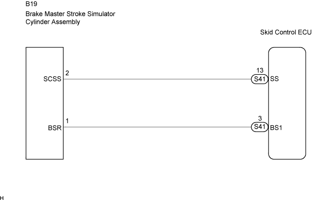
| 1.INSPECT BRAKE MASTER STROKE SIMULATOR CYLINDER ASSEMBLY |
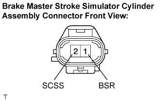 |
Disconnect the brake master stroke simulator cylinder assembly connector.
Measure the resistance according to the value(s) in the table below.
| Tester Connection | Specified Condition |
| 1 (BSR) - 2 (SCSS) | 21.45 to 23.15 Ω |
|
| ||||
| OK | |
| 2.CHECK HARNESS AND CONNECTOR (BETWEEN SKID CONTROL ECU AND STROKE SIMULATOR CYLINDER) |
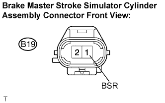 |
Connect the brake master stroke simulator cylinder assembly connector.
Measure the voltage according to the value(s) in the table below.
| Tester Connection | Condition | Specified Condition |
| B19-1 (BSR) - Body ground | Ignition switch ON | 10 to 14 V |
|
| ||||
| OK | |
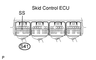
| 3.INSPECT SKID CONTROL ECU (SS TERMINAL) |
 |
Connect the intelligent tester to the DLC3.
Select the ACTIVE TEST mode on the intelligent tester.
| Item | Vehicle Condition / Test Details | Diagnostic Note |
| ECB Solenoid (SCSS) | Stroke simulator cut valve pattern activation ON / OFF | Operating of solenoid (clicking sound) can be heard |
Using the intelligent tester, turn the stroke simulator cylinder assembly ON/OFF.
Measure the voltage according to the value(s) in the table below.
| Tester Connection | Condition | Specified Condition |
| S41-13 (SS) - Body ground | Brake Master Stroke Simulator Cylinder assembly ON | Below 1.5 V |
| S41-13 (SS) - Body ground | Brake Master Stroke Simulator Cylinder assembly OFF | 10 to 14 V |
|
| ||||
| OK | ||
| ||
