DTC C1378/44 Capacitor Communication Malfunction |
| DTC No. | INF Code | DTC Detecting Condition | Trouble Area |
| C1378/44 | 112 |
|
|
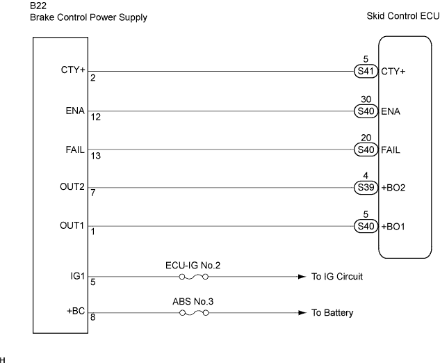
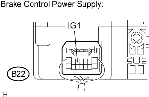
| 1.INSPECT BRAKE CONTROL POWER SUPPLY (IG1 TERMINAL) |
 |
Measure the voltage according to the value(s) in the table below.
| Tester Connection | Condition | Specified Condition |
| B22-5 (IG1) - Body ground | Ignition switch ON | 10 to 14 V |
|
| ||||
| OK | |
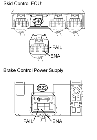
| 2.CHECK HARNESS AND CONNECTOR (BETWEEN SKID CONTROL ECU AND BRAKE CONTROL POWER SUPPLY) |
 |
Turn the ignition switch off.
Disconnect the skid control ECU connector and brake control power supply connector.
Measure the resistance according to the value(s) in the table below.
| Tester Connection | Specified Condition |
| S40-30 (ENA) - B22-12 (ENA) | Below 1 Ω |
| S40-20 (FAIL) - B22-13 (FAIL) | Below 1 Ω |
Measure the resistance according to the value(s) in the table below.
| Tester Connection | Specified Condition |
| S40-30 (ENA) - Body ground | 10 kΩ or higher |
| S40-20 (FAIL) - Body ground | 10 kΩ or higher |
|
| ||||
| OK | |
| 3.CHECK FREEZE FRAME DATA |
Check the INF code from the FREEZE FRAME DATA memorized when the DTC (C1378/44) is stored (Click here).
| Condition | Proceed To |
| INF codes are not output | A |
| INF code (112) is output | B |
|
| ||||
| A | ||
| ||
