DTC P3004-800 Power Cable Malfunction |
DTC P3004-801 Power Cable Malfunction |
| DTC No. | INF Code | DTC Detection Condition | Trouble Area |
| P3004 | 800 | Excessive overcurrent in high-voltage system |
|
| P3004 | 801 | Minimal overcurrent in high-voltage system |
|
| 1.READ OUTPUT DTC (HV AND EMPS) |
Connect the intelligent tester to the DLC3.
Turn the ignition switch to the ON position.
Select the following menu items: Powertrain / Hybrid Control and EMPS / DTC.
|
| ||||
| NO | |
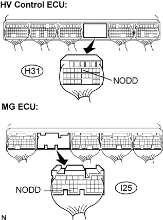
| 2.CHECK WIRE HARNESS AND CONNECTOR (HV CONTROL ECU - MG ECU) |
 |
Turn the ignition switch off and remove the service plug grip. (Click here)
Disconnect the H31 connector from the HV control ECU.
Remove the inverter cover. (Click here)
Disconnect the I25 connector from the MG ECU.
Measure the voltage according to the value(s) in the table below when the ignition switch is in the ON position.
| Tester Connection | Specified Condition |
| NODD (H31-11) - Body ground | Below 1 V |
Turn the ignition switch off.
Measure the resistance according to the value(s) in the table below.
| Tester Connection | Specified Condition |
| NODD (H31-11) - NOFF (I25-33) | Below 1 Ω |
| Tester Connection | Specified Condition |
| NODD (H31-11) or NOFF (I25-33) - Body ground | 10 kΩ or higher |
|
| ||||
| OK | |
| 3.CHECK W/ MOTOR COMPRESSOR ASSEMBLY |
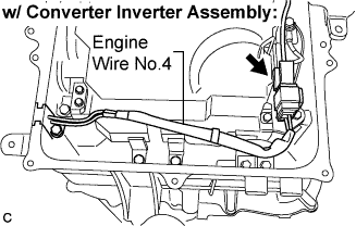 |
Disconnect the engine wire No.4 from the air conditioner wiring harness.
 |
Measure the resistance according to the value(s) in the table below.
| Tester Connection | Specified Condition |
| 1(+) - 2(-) | 100 Ω or higher |
|
| ||||
| OK | |
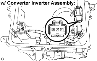
| 4.CHECK ENGINE WIRE NO.4 |
 |
Disconnect the engine wire No.4 from the w/ motor compressor assembly.
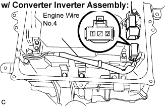 |
Measure the resistance according to the value(s) in the table below.
| Tester Connection | Specified Condition |
| 1 - 2 | 10 kΩ or higher |
|
| ||||
| OK | ||
| ||
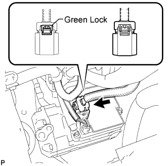
| 5.CHECK FRAME WIRE NO.3 |
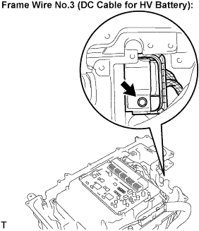 |
Disconnect the frame wire No.3 (DC cable for the HV battery) from the w/ converter inverter assembly.
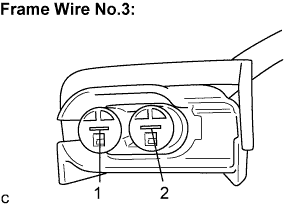 |
Measure the resistance according to the value(s) in the table below.
| Tester Connection | Specified Condition |
| 1(+) - 2(-) | 100 Ω or higher |
|
| ||||
| NG | |
| 6.CHECK FRAME WIRE NO.3 (W/ CONVERTER INVERTER - HV RELAY ASSEMBLY) |
 |
Disconnect the frame wire No.3 (DC cable for the w/ converter inverter assembly) from the HV relay assembly.
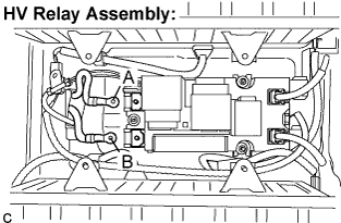 |
Measure the resistance according to the value(s) in the table below.
| Tester Connection | Specified Condition |
| A - B | 10 kΩ or higher |
|
| ||||
| OK | |
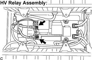
| 7.CHECK HV RELAY ASSEMBLY |
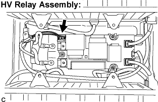 |
Disconnect the frame wire No.3 (connector for the power steering converter assembly) from the HV relay assembly.
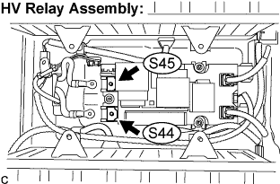 |
Measure the resistance according to the value(s) in the table below.
| Tester Connection | Specified Condition |
| S45-1 - S44-1 | 10 kΩ or higher |
|
| ||||
| OK | |
| 8.CHECK FRAME WIRE NO.3 (HV RELAY ASSEMBLY - POWER STEERING CONVERTER) |
 |
Disconnect the frame wire No.3 (connector for the HV battery) from the power steering converter assembly.
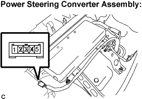 |
Measure the resistance according to the value(s) in the table below.
| Tester Connection | Specified Condition |
| 1 - 5 | 10 kΩ or higher |
|
| ||||
| OK | ||
| ||
