DTC P0A78-504 Drive Motor "A" Inverter Performance |
| DTC No. | INF Code | DTC Detection Condition | Trouble Area |
| P0A78 | 504 | Motor inverter overvoltage signal detection (overvoltage by HV transaxle assembly malfunction) |
|
| 1.READ OUTPUT DTC (HV) |
Connect the intelligent tester to the DLC3.
Turn the ignition switch to the ON position.
Select the following menu items: Powertrain / Hybrid Control / DTC.
Read output DTCs. (Click here)
| DTC No. | INF Code | Detection Item |
| P0A3F | 243 | Motor resolver circuit |
| P0A40 | 500 | Motor resolver output is out of normal range |
| P0A41 | 245 | Motor resolver malfunction (Low) |
| P0A45 | 669 | Interphase short in Rear Motor resolver circuit |
| P0A46 | 671 | Rear motor resolver output is out of normal range |
| P0A47 | 670 | Rear motor resolver malfunction (Low) |
| P0A4B | 253 | Generator resolver circuit |
| P0A4C | 513 | Generator resolver output is out of normal range |
| P0A4D | 255 | Generator resolver malfunction (Low) |
| P0A78 | 266, 280 | Motor inverter function malfunction |
| P0A94 | 558, 559, 588, 589 | Boost converter circuit malfunction |
| P0A95 | 123 | High voltage fuse blown out |
| P0AA1 | 226 | SMR+ stuck closed |
| P0AA2 | 227 | SMR+ stuck open |
| P0AA4 | 228 | SMR- stuck closed |
| P0AA5 | 229 | SMR- stuck open |
| P3004 | 803 | High-current wiring malfunction |
|
| ||||
| NO | |
| 2.CHECK CONNECTION CONDITION OF MG ECU CONNECTOR (LOOSENESS AND POOR CONTACT) |
Turn the ignition switch off and remove the service plug grip. (Click here)
Remove the inverter cover. (Click here)
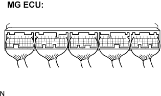 |
Check the connections of the MG ECU connectors.
|
| ||||
| OK | |
| 3.INSPECT HV RELAY ASSEMBLY (SMR2) |
Check that the service plug grip is removed.
Remove the HV relay assembly from the vehicle. (Click here)
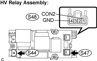 |
Measure the resistance according to the value(s) in the table below.
| Tester Condition | Specified Condition |
| S47-1 - S44-1 | Below 1 Ω (Apply auxiliary battery voltage between terminals (CON2 (S48-1) and GND (S48-4)) |
Measure the resistance according to the value(s) in the table below.
| Tester Condition | Specified Condition |
| CON2 (S48-1) - GND (S48-4) | 20 to 60 Ω at -35 to 80°C ( -31 to 176°F) |
|
| ||||
| OK | |
| 4.INSPECT HV RELAY ASSEMBLY (SMR3) |
Check that the service plug grip is removed.
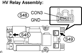 |
Measure the resistance according to the value(s) in the table below.
| Tester Condition | Specified Condition |
| S49-1 - S45-1 | Below 1 Ω (Apply auxiliary battery voltage between terminals (CON3 (S48-2) and GND (S48-4)) |
Measure the resistance according to the value(s) in the table below.
| Tester Condition | Specified Condition |
| CON3 (S48-2) - GND (S48-4) | 20 to 60 Ω at -35 to 80°C ( -31 to 176°F) |
|
| ||||
| OK | |
| 5.CONFIRM INFORMATION (EXCLUSIVE INFO 4) |
Connect the intelligent tester to the DLC3.
Turn the ignition switch to the ON position and check for HV system DTC P0A0D-350 by following the prompts on the intelligent tester screen.
Display freeze frame data corresponding to DTC P0A94 and select the information.
Select INF code 556 and read "Exclusive Info 4".
| Displayed item in exclusive information 4 | Proceed to |
| -63 to 64 | A |
| 65 to 128 | B |
|
| ||||
| A | |
| 6.CHECK HARNESS AND CONNECTOR (MG ECU - MOTOR RESOLVER) |
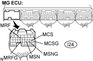 |
Disconnect the I24 connector from the MG ECU.
Measure the voltage according to the value(s) in the table below when the ignition switch is in the ON position.
| Tester Connection | Specified Condition |
| MRF (I24-13) - Body ground | Below 1 V |
| MRFG (I24-23) - Body ground | Below 1 V |
| MSN (I24-21) - Body ground | Below 1 V |
| MSNG (I24-20) - Body ground | Below 1V |
| MCS (I24-19) - Body ground | Below 1 V |
| MCSG (I24-18) - Body ground | Below 1 V |
Turn the ignition switch off.
Measure the resistance according to the value(s) in the table below.
| Tester Connection | Specified Condition |
| MRF (I24-13) - MRFG (I24-23) | 7.65 to 10.2 Ω |
| MSN (I24-21) - MSNG (I24-20) | 12.6 to 16.8 Ω |
| MCS (I24-19) - MCSG (I24-18) | 12.6 to 16.8 Ω |
Measure the resistance according to the value(s) in the table below.
| Tester Connection | Specified Condition |
| MRF (I24-13) or MRFG (I24-23) - Body ground | 10 kΩ or higher |
| MSN (I24-21) or MSNG (I24-20) - Body ground | 10 kΩ or higher |
| MCS (I24-19) or MCSG (I24-18) - Body ground | 10 kΩ or higher |
|
| ||||
| OK | |
| 7.CHECK HARNESS AND CONNECTOR (MG ECU -GENERATOR RESOLVER) |
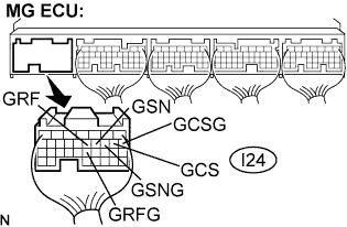 |
Disconnect the I24 connector from the MG ECU.
Measure the voltage according to the value(s) in the table below when the ignition switch is in the ON position.
| Tester Connection | Specified Condition |
| GRF (I24-12) - Body ground | Below 1 V |
| GRFG (I24-23) - Body ground | Below 1 V |
| GSN (I24-11) - Body ground | Below 1 V |
| GSNG (I24-10) - Body ground | Below 1V |
| GCS (I24-9) - Body ground | Below 1 V |
| GCSG (I24-8) - Body ground | Below 1 V |
Turn the ignition switch off.
Measure the resistance according to the value(s) in the table below.
| Tester Connection | Specified Condition |
| GRF (I24-12) - GRFG (I24-22) | 7.65 to 10.2 Ω |
| GSN (I24-11) - GSNG (I24-10) | 12.6 to 16.8 Ω |
| GCS (I24-9) - GCSG (I24-8) | 12.6 to 16.8 Ω |
Measure the resistance according to the value(s) in the table below.
| Tester Connection | Specified Condition |
| GRF (I24-12) or GRFG (I24-22) - Body ground | 10 kΩ or higher |
| GSN (I24-11) or GSNG (I24-10) - Body ground | 10 kΩ or higher |
| GCS (I24-9) or GCSG (I24-8) - Body ground | 10 kΩ or higher |
|
| ||||
| OK | ||
| ||
| 8.CHECK HARNESS AND CONNECTOR (MG ECU - REAR MOTOR RESOLVER) |
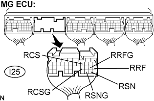 |
Disconnect the I25 connector from the MG ECU.
Measure the voltage according to the value(s) in the table below when the ignition switch is in the ON position.
| Tester Connection | Specified Condition |
| RRF (I25-21) - Body ground | Below 1 V |
| RRFG (I25-22) - Body ground | Below 1 V |
| RSN (I25-29) - Body ground | Below 1 V |
| RSNG (I25-30) - Body ground | Below 1V |
| RCS (I25-11) - Body ground | Below 1 V |
| RCSG (I25-23) - Body ground | Below 1 V |
Turn the ignition switch off.
Measure the resistance according to the value(s) in the table below.
| Tester Connection | Specified Condition |
| RRF (I25-21) - Body ground | 7.65 to 10.2 Ω |
| RSN (I25-29) - Body ground | 12.6 to 16.8 Ω |
| RCS (I25-11) - Body ground | 12.6 to 16.8 Ω |
Measure the resistance according to the value(s) in the table below.
| Tester Connection | Specified Condition |
| RRF (I25-21) or RRFG (I25-22) - Body ground | 10 kΩ or higher |
| RSN (I25-29) or RSNG (I25-30) - Body ground | 10 kΩ or higher |
| RCS (I25-11) or RCSG (I25-23) - Body ground | 10 kΩ or higher |
|
| ||||
| OK | ||
| ||
| 9.INSPECT MOTOR RESOLVER |
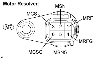 |
Disconnect the M7 motor resolver connector.
Measure the resistance according to the value(s) in the table below.
| Tester Connection | Specified Condition |
| MRF (M7-1) - MRFG (M7-4) | 7.65 to 10.2 Ω |
| MSN (M7-2) - MSNG (M7-5) | 12.6 to 16.8 Ω |
| MCS (M7-3) - MCSG (M7-6) | 12.6 to 16.8 Ω |
Using a megohmmeter, measure the insulation resistance according to the value(s) in the table below.
| Tester Connection | Specified Condition |
| MRF (M7-1) - MSN (M7-2) | 10 MΩ or higher |
| MRF (M7-1) - MCS (M7-3) | 10 MΩ or higher |
| MSN (M7-2) - MCS (M7-3) | 10 MΩ or higher |
| MRFG (M7-4) - MSNG (M7-5) | 10 MΩ or higher |
| MRFG (M7-4) - MCSG (M7-6) | 10 MΩ or higher |
| MSNG (M7-5) - MCSG (M7-6) | 10 MΩ or higher |
| Each terminal listed above - transaxle housing | 10 MΩ or higher |
|
| ||||
| OK | ||
| ||
| 10.INSPECT GENERATOR RESOLVER |
Remove the w/ converter inverter assembly. (Click here)
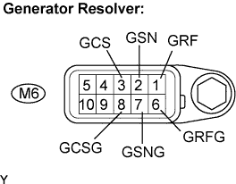 |
Disconnect the M6 generator resolver connector.
Measure the resistance according to the value(s) in the table below.
| Tester Connection | Specified Condition |
| GRF (M6-1) - GRFG (M6-6) | 7.65 to 10.2 Ω |
| GSN (M6-2) - GSNG (M6-7) | 12.6 to 16.8 Ω |
| GCS (M6-3) - GCSG (M6-8) | 12.6 to 16.8 Ω |
Using a megohmmeter, measure the insulation resistance according to the value(s) in the table below.
| Tester Connection | Specified Condition |
| GRF (M6-1) - GSN (M6-2) | 10 MΩ or higher |
| GRF (M6-1) - GCS (M6-3) | 10 MΩ or higher |
| GSN (M6-2) - GCS (M6-3) | 10 MΩ or higher |
| GRFG (M6-6) - GSNG (M6-7) | 10 MΩ or higher |
| GRFG (M6-6) - GCSG (M6-8) | 10 MΩ or higher |
| GSNG (M6-7) - GCSG (M6-8) | 10 MΩ or higher |
| Each terminal listed above - transaxle housing | 10 MΩ or higher |
|
| ||||
| OK | ||
| ||
| 11.INSPECT REAR MOTOR RESOLVER |
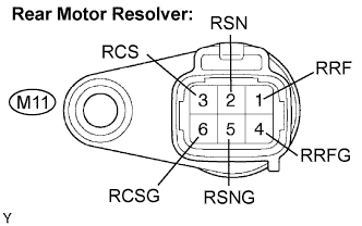 |
Disconnect the M11 rear motor resolver connector.
Measure the resistance according to the value(s) in the table below.
| Tester Connection | Specified Condition |
| RRF (M11-1) - RRFG (M11-4) | 7.65 to 10.2 Ω |
| RSN (M11-2) - RSNG (M11-5) | 12.6 to 16.8 Ω |
| RCS (M11-3) - RCSG (M11-6) | 12.6 to 16.8 Ω |
Using a megohmmeter, measure the insulation resistance according to the value(s) in the table below.
| Tester Connection | Specified Condition |
| MRF (M11-1) - MSN (M11-2) | 10 MΩ or higher |
| RRF (M11-1) - RCS (M11-3) | 10 MΩ or higher |
| RSN (M11-2) - RCS (M11-3) | 10 MΩ or higher |
| RRFG (M11-4) - RSNG (M11-5) | 10 MΩ or higher |
| RRFG (M11-4) - RCSG (M11-6) | 10 MΩ or higher |
| RSNG (M11-5) - RCSG (M11-6) | 10 MΩ or higher |
| Each terminal listed above - transaxle housing | 10 MΩ or higher |
|
| ||||
| OK | ||
| ||
