DTC P0A94-549 DC / DC Converter Performance |
| DTC No. | INF Code | DTC Detection Condition | Trouble Area |
| P0A94 | 549 | Boost converter overvoltage signal detection (overvoltage by HV transaxle assembly malfunction) |
|
| 1.READ OUTPUT DTC (HV) |
Connect the intelligent tester to the DLC3.
Turn the ignition switch to the ON position.
Select the following menu items: Powertrain / Hybrid Control / DTC.
Read output DTCs. (Click here)
| DTC No. | INF Code | Detection Item |
| P0A3F | 243 | Motor resolver circuit |
| P0A40 | 500 | Motor resolver output is out of normal range |
| P0A41 | 245 | Motor resolver malfunction (Low) |
| P0A45 | 669 | Interphase short in Rear Motor resolver circuit |
| P0A46 | 671 | Rear motor resolver output is out of normal range |
| P0A47 | 670 | Rear motor resolver malfunction (Low) |
| P0A4B | 253 | Generator resolver circuit |
| P0A4C | 513 | Generator resolver output is out of normal range |
| P0A4D | 255 | Generator resolver malfunction (Low) |
| P0A78 | 266, 280 | Motor inverter function malfunction |
| P0A94 | 558, 559, 588, 589 | Boost converter circuit malfunction |
| P0A95 | 123 | High voltage fuse blown out |
| P0AA1 | 226 | SMR+ stuck closed |
| P0AA2 | 227 | SMR+ stuck open |
| P0AA4 | 228 | SMR- stuck closed |
| P0AA5 | 229 | SMR- stuck open |
| P3004 | 803 | High-current wiring malfunction |
|
| ||||
| NO | |
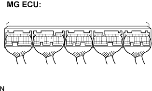
| 2.CHECK CONNECTION CONDITION OF MG ECU CONNECTOR (LOOSENESS AND POOR CONTACT) |
 |
Turn the ignition switch off and remove the service plug grip. (Click here)
Remove the inverter cover. (Click here)
Check the connections of all MG ECU connectors.
|
| ||||
| NG | |
| 3.INSPECT HV RELAY ASSEMBLY (SMR2) |
Check that the service plug grip is removed.
Remove the HV relay assembly from the vehicle. (Click here)
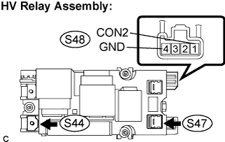 |
Measure the resistance according to the value(s) in the table below.
| Tester Connection | Specified Condition |
| S47-1 - S44-1 | Below 1 Ω (Apply auxiliary battery voltage between terminals CON2 (S48-1) and GND (S48-4)) |
Measure the resistance according to the value(s) in the table below.
| Tester Connection | Specified Condition |
| CON2 (S48-1) - GND (S48-4) | 20 to 60 Ω at -35 to 80°C ( -31 to 176°F) |
|
| ||||
| OK | |
| 4.INSPECT HV RELAY ASSEMBLY (SMR3) |
Check that the service plug grip is removed.
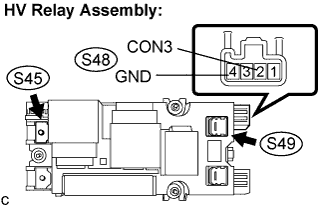 |
Measure the resistance according to the value(s) in the table below.
| Tester Connection | Specified Condition |
| S49-1 - S45-1 | Below 1 Ω (Apply auxiliary battery voltage between terminals CON3 (S48-2) and GND (S48-4)) |
Measure the resistance according to the value(s) in the table below.
| Tester Connection | Specified Condition |
| CON3 (S48-2) - GND (S48-4) | 20 to 60 Ω at -35 to 80°C ( -31 to 176°F) |
|
| ||||
| OK | |
| 5.CONFIRM INFORMATION (EXCLUSIVE INFO 4) |
Connect the intelligent tester to the DLC3.
Turn the ignition switch to the ON position.
Select the following menu items: Powertrain / Hybrid Control / DTC.
Read output DTCs.
Display freeze frame data corresponding to DTC P0A94 and select the information.
Select INF code 556 and read "Exclusive Info 4".
| Displayed item in exclusive information 4 | Proceed to |
| -63 to 64 | A |
| 65 to 128 | B |
|
| ||||
| A | |
| 6.CHECK HARNESS AND CONNECTOR (MG ECU - MOTOR RESOLVER) |
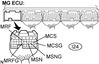 |
Disconnect the I24 connector from the MG ECU.
Measure the voltage according to the value(s) in the table below when the ignition switch is in the ON position.
| Tester Connection | Specified Condition |
| MRF (I24-13) - Body ground | Below 1 V |
| MRFG (I24-23) - Body ground | Below 1 V |
| MSN (I24-21) - Body ground | Below 1 V |
| MSNG (I24-20) - Body ground | Below 1 V |
| MCS (I24-19) - Body ground | Below 1V |
| MCSG (I24-18) - Body ground | Below 1 V |
Turn the ignition switch off.
Measure the resistance according to the value(s) in the table below.
| Tester Connection | Specified Condition |
| MRF (I24-13) - MRFG (I24-23) | 7.65 to 10.2 Ω |
| MSN (I24-21) - MSNG (I24-20) | 12.6 to 16.8 Ω |
| MCS (I24-19) - MCSG (I24-18) | 12.6 to 16.8 Ω |
Measure the resistance according to the value(s) in the table below.
| Tester Connection | Specified Condition |
| MRF (I24-13) or MRFG (I24-23) - Body ground | 10 kΩ or higher |
| MSN (I24-21) or MSNG (I24-20) - Body ground | 10 kΩ or higher |
| MCS (I24-19) or MCSG (I24-18) - Body ground | 10 kΩ or higher |
|
| ||||
| OK | |
| 7.CHECK HARNESS AND CONNECTOR (MG ECU - GENERATOR RESOLVER) |
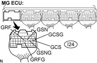 |
Disconnect the I24 connector from the MG ECU.
Measure the voltage according to the value(s) in the table below when the ignition switch is in the ON position.
| Tester Connection | Specified Condition |
| GRF (I24-12) - Body ground | Below 1 V |
| GRFG (I24-22) - Body ground | Below 1 V |
| GSN (I24-11) - Body ground | Below 1 V |
| GSNG (I24-10) - Body ground | Below 1 V |
| GCS (I24-9) - Body ground | Below 1 V |
| GCSG (I24-8) - Body ground | Below 1 V |
Turn the ignition switch off.
Measure the resistance according to the value(s) in the table below.
| Tester Connection | Specified Condition |
| GRF (I24-12) - GRFG (I24-22) | 7.65 to 10.2 Ω |
| GSN (I24-11) - GSNG (I24-10) | 12.6 to 16.8 Ω |
| GCS (I24-9) - GCSG (I24-8) | 12.6 to 16.8 Ω |
Measure the resistance according to the value(s) in the table below.
| Tester Connection | Specified Condition |
| GRF (I24-12) or GRFG (I24-22) - Body ground | 10 kΩ or higher |
| GSN (I24-11) or GSNG (I24-10) - Body ground | 10 kΩ or higher |
| GCS (I24-9) or GCSG (I24-8) - Body ground | 10 kΩ or higher |
|
| ||||
| OK | ||
| ||
| 8.CHECK HARNESS AND CONNECTOR (MG ECU - REAR MOTOR RESOLVER) |
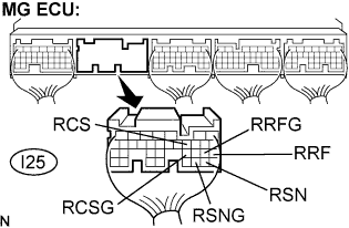 |
Disconnect the I25 connector from the MG ECU.
Measure the voltage according to the value(s) in the table below when the ignition switch is in the ON position.
| Tester Connection | Specified Condition |
| RRF (I25-21) - Body ground | Below 1 V |
| RRF (I25-21) - Body ground | Below 1 V |
| RSN (I25-29) - Body ground | Below 1 V |
| RSNG (I25-30) - Body ground | Below 1 V |
| RCS (I25-11) - Body ground | Below 1 V |
| RCSG (I25-23) - Body ground | Below 1 V |
Turn the ignition switch off.
Measure the resistance according to the value(s) in the table below.
| Tester Connection | Specified Condition |
| RRF (I25-21) - RRFG (I25-22) | 7.65 to 10.2 Ω |
| RSN (I25-29) - RSNG (I25-30) | 12.6 to 16.8 Ω |
| RCS (I25-11) - RCSG (I25-23) | 12.6 to 16.8 Ω |
Measure the resistance according to the value(s) in the table below.
| Tester Connection | Specified Condition |
| RRF (I25-21) or RRFG (I25-22) - Body ground | 10 kΩ or higher |
| RSN (I25-29) or RSNG (I25-30) - Body ground | 10 kΩ or higher |
| RCS (I25-11) or RCSG (I25-23) - Body ground | 10 kΩ or higher |
|
| ||||
| OK | ||
| ||
| 9.INSPECT MOTOR RESOLVER |
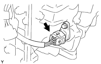 |
Disconnect the M7 motor resolver connector.
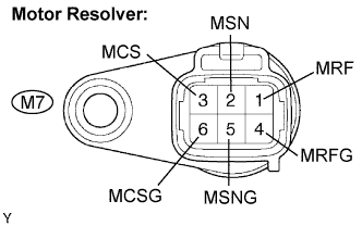 |
Measure the resistance according to the value(s) in the table below.
| Tester Connection | Specified Condition |
| MRF (M7-1) - MRFG (M7-4) | 7.65 to 10.2 Ω |
| MSN (M7-2) - MSNG (M7-5) | 12.6 to 16.8 Ω |
| MCS (M7-3) - MCSG (M7-6) | 12.6 to 16.8 Ω |
Using a megohmmeter, measure the insulation resistance according to the value(s) in the table below.
| Tester Connection | Specified Condition |
| MRF (M7-1) - MSN (M7-2) | 10 MΩ or higher |
| MRF (M7-1) - MCS (M7-3) | 10 MΩ or higher |
| MSN (M7-2) - MCS (M7-3) | 10 MΩ or higher |
| MRFG (M7-4) - MSNG (M7-5) | 10 MΩ or higher |
| MRFG (M7-4) - MCSG(M7-6) | 10 MΩ or higher |
| MSNG (M7-5) - MCSG (M7-6) | 10 MΩ or higher |
| Each terminal listed above - Transaxle housing | 10 MΩ or higher |
|
| ||||
| OK | ||
| ||
| 10.INSPECT GENERATOR RESOLVER |
 |
Remove the w/ converter inverter assembly.
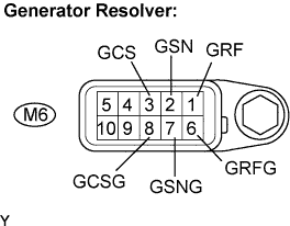 |
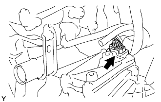
Disconnect the M6 generator resolver connector.
Measure the resistance according to the value(s) in the table below.
| Tester Connection | Specified Condition |
| GRF (M6-1) - GRFG (M6-6) | 7.65 to 10.2 Ω |
| GSN (M6-2) - GSNG (M6-7) | 12.6 to 16.8 Ω |
| GCS (M6-3) - GCSG (M6-8) | 12.6 to 16.8 Ω |
Using a megohmmeter, measure the insulation resistance according to the value(s) in the table below.
| Tester Connection | Specified Condition |
| GRF (M6-1) - GSN (M6-2) | 10 MΩ or higher |
| GRF (M6-1) - GCS (M6-3) | 10 MΩ or higher |
| GSN (M6-2) - GCS (M6-3) | 10 MΩ or higher |
| GRFG (M6-6) - GSNG (M6-7) | 10 MΩ or higher |
| GRFG (M6-6) - GCSG (M6-8) | 10 MΩ or higher |
| GSNG (M6-7) - GCSG (M6-8) | 10 MΩ or higher |
| Each terminal listed above - Transaxle housing | 10 MΩ or higher |
|
| ||||
| OK | ||
| ||
| 11.INSPECT REAR MOTOR RESOLVER |
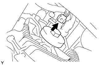 |
Disconnect the M11 rear motor resolver connector.
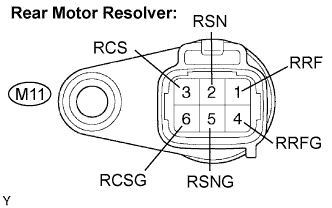 |
Measure the resistance according to the value(s) in the table below.
| Tester Connection | Specified Condition |
| RRF (M11-1) - RRFG (M11-4) | 7.65 to 10.2 Ω |
| RSN (M11-2) - RSNG (M11-5) | 12.6 to 16.8 Ω |
| RCS (M11-3) - RCSG (M11-6) | 12.6 to 16.8 Ω |
Using a megohmmeter, measure the insulation resistance according to the value(s) in the table below.
| Tester Connection | Specified Condition |
| RRF (M11-1) - RSN (M11-2) | 10 MΩ or higher |
| RRF (M11-1) - RCS (M11-3) | 10 MΩ or higher |
| RSN (M11-2) - RCS (M11-3) | 10 MΩ or higher |
| RRFG (M11-4) - RSNG (M11-5) | 10 MΩ or higher |
| RRFG (M11-4) - RCSG (M11-6) | 10 MΩ or higher |
| RSNG (M11-5) - RCSG (M11-6) | 10 MΩ or higher |
| Each terminal listed above - Transaxle housing | 10 MΩ or higher |
|
| ||||
| OK | ||
| ||
