ELECTRICAL BACK DOOR OUTSIDE HANDLE SYSTEM > Back Door Lock Motor Circuit |
| 1.INSPECT BACK DOOR LOCK ASSEMBLY |
 |
Remove the back door lock assembly.
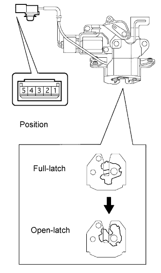
Using a screwdriver, push the latch in order to put the back door lock in the locked condition (full-latch position).
Apply battery voltage and check operation of the door lock motor.
| Measurement Condition | Specified Condition |
| Battery positive (+) → Terminal 5 Battery negative (-) → Terminal 3 | Latch turns to open-latch position |
 |
Remove the back door lock assembly.
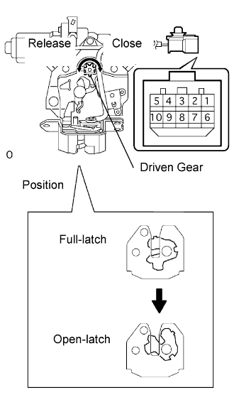
Using a screwdriver, push the latch in order to put the back door lock in the locked condition (full-latch position).
Apply battery voltage and check operation of the door lock motor.
| Measurement Condition | Specified Condition |
| Battery positive (+) → Terminal 7 Battery negative (-) → Terminal 5 | Latch turns to open-latch position |
Check motor operation when battery voltage is applied to the terminals.
| Measurement Condition | Specified Condition |
| Battery positive (+) → Terminal 5 Battery negative (-) → Terminal 7 | Close operation (Clockwise) |
| Battery positive (+) → Terminal 7 Battery negative (-) → Terminal 5 | Release operation (Counterclockwise rotation) |
|
| ||||
| OK | |
| 2.CHECK WIRE HARNESS |
 |
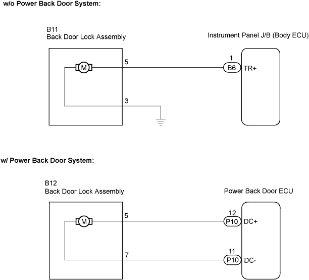
w/o Power back door system:
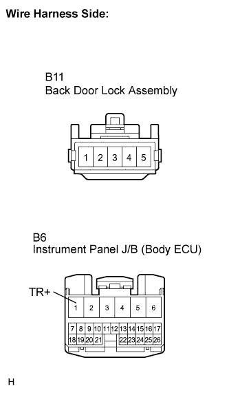
Disconnect the back door lock assembly connector.
Disconnect the instrument panel J/B connector.
Measure the resistance according to the value(s) in the table below.
| Tester Connection | Condition | Specified Condition |
| B11-5 - B6-1 (TR+) | Always | Below 1 Ω |
| B11-3 - Body ground | Always | Below 1 Ω |
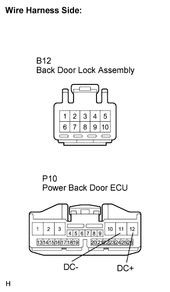 |
w/ Power back door system:
Disconnect the back door lock assembly connector.
Disconnect the power back door ECU connector.
Measure the resistance according to the value(s) in the table below.
| Tester Connection | Condition | Specified Condition |
| B12-5 - P10-12 (DC+) | Always | Below 1 Ω |
| B12-7 - P10-11 (DC-) | Always | Below 1 Ω |
|
| ||||
| OK | ||
| ||
