POWER DOOR LOCK CONTROL SYSTEM > Driver Side Door Key Lock and Unlock Switch Circuit |
| 1.READ VALUE OF DATA LIST |
Check the DATA LIST to ensure proper operation of the door unlock detection switch.
| Item | Measurement Item / Display (Range) | Normal Condition | Diagnostic Note |
| Door Key Linked Lock SW | Driver door lock/unlock switch lock signal (key-linked-lock switch) /ON or OFF | ON: Driver side door key cylinder is turned to LOCK OFF: Driver side door key cylinder is not turned to LOCK | - |
| Door Key Linked Unlock SW | Driver door lock/unlock switch unlock signal (key-linked-unlock switch) /ON or OFF | ON: Driver side door key cylinder is turned to UNLOCK OFF: Driver side door key cylinder is not turned to UNLOCK | - |
|
| ||||
| OK | ||
| ||
| 2.INSPECT FRONT DOOR LOCK ASSEMBLY (DOOR KEY LOCK AND UNLOCK SWITCH) |
LHD Models:
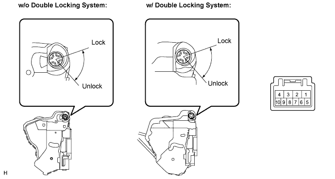
Measure the resistance according to the value(s) in the table below.
| Tester Connection | Condition | Specified Condition |
| 7 - 9 | ON (Door lock set to LOCK) | Below 1 Ω |
| 7 - 9, 7 - 10 | OFF (Free) | 10 kΩ or higher |
| 7 - 10 | ON (Door lock set to UNLOCK) | Below 1 Ω |
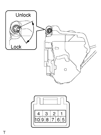 |
RHD Models:
Remove the front door lock assembly RH.
Measure the resistance according to the value(s) in the table below.
| Tester Connection | Condition | Specified Condition |
| 8 - 6 | ON (Door lock set to LOCK) | Below 1 Ω |
| 8 - 6, 8 - 5 | OFF (Free) | 10 kΩ or higher |
| 8 - 5 | ON (Door lock set to UNLOCK) | Below 1 Ω |
|
| ||||
| OK | |
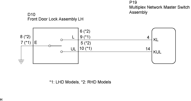
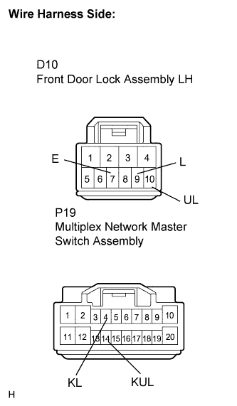
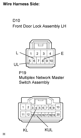
| 3.CHECK WIRE HARNESS (FRONT DOOR LOCK ASSEMBLY - MULTIPLEX NETWORK MASTER SWITCH) |
 |
LHD Models:
Disconnect the front door lock assembly LH connector.
Disconnect the multiplex network master switch assembly connector.
Measure the resistance according to the value(s) in the table below.
| Tester Connection | Condition | Specified Condition |
| D10-9 (L) - P19-4 (KL) | Always | Below 1 Ω |
| D10-10 (UL) - P19-14 (KUL) | Always | Below 1 Ω |
| D10-7(E) - Body ground | Always | Below 1 Ω |
 |
RHD Models:
Disconnect the front door lock assembly RH connector.
Disconnect the multiplex network master switch assembly connector.
Measure the resistance according to the value(s) in the table below.
| Tester Connection | Condition | Specified Condition |
| D10-6 (L) - P19-4 (KL) | Always | Below 1 Ω |
| D10-5 (UL) - P19-14 (KUL) | Always | Below 1 Ω |
| D10-8(E) - Body ground | Always | Below 1 Ω |
|
| ||||
| OK | ||
| ||
