POWER DOOR LOCK CONTROL SYSTEM > Door Control Switch Circuit |
| 1.READ VALUE OF DATA LIST (FRONT PASSENGER SIDE DOOR CONTROL SWITCH ASSEBLY) |
Check the DATA LIST to ensure proper operation of the front passenger door lock switch.
| Item | Measurement Item / Display (Range) | Normal Condition | Diagnostic Note |
| Door Lock SW-Lock | Door lock switch signal /ON or OFF | ON: Door lock switch is pushed to LOCK position OFF: Door lock switch is not pushed to LOCK position | - |
| Door Lock SW-Unlock | Door unlock switch signal /ON or OFF | ON: Door lock switch is pushed to UNLOCK position OFF: Door lock switch is not pushed to UNLOCK position | - |
|
| ||||
| OK | ||
| ||
| 2.INSPECT DOOR CONTROL SWITCH ASSEMBLY |
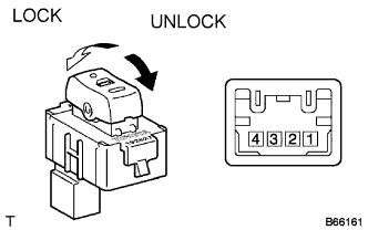 |
Remove the door control switch assembly.
Measure the resistance according to the value(s) in the table below.
| Tester Connection | Condition | Specified Condition |
| 3 (LOCK) - 2 | Lock | Below 1 Ω |
| 3 (LOCK) - 2 1 (UNLOCK) - 2 | OFF (Free) | 10 kΩ or higher |
| 1 (UNLOCK) - 2 | Unlock | Below 1 Ω |
|
| ||||
| OK | |
| 3.CHECK WIRE HARNESS (DOOR CONTROL SWITCH ASSEMBLY - INSTRUMENT PANEL J/B) |
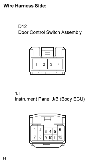 |
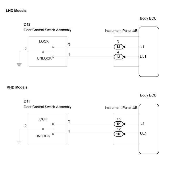
LHD Models:
Disconnect the door control switch assembly connector.
Disconnect the instrument panel J/B connector.
Measure the resistance according to the value(s) in the table below.
| Tester Connection | Condition | Specified Condition |
| D12-3 - 1J-3 | Always | Below 1 Ω |
| D12-1 - 1J-4 | Always | Below 1 Ω |
| D12-2 - Body ground | Always | Below 1 Ω |
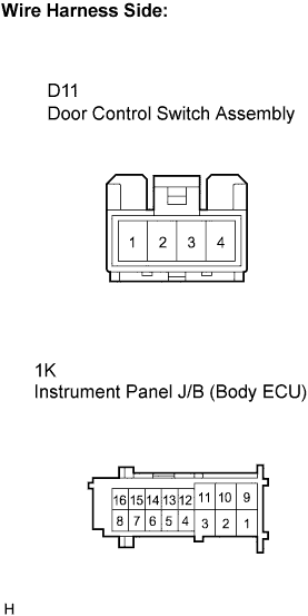 |
RHD Models:
Disconnect the door control switch assembly connector.
Disconnect the instrument panel J/B connector.
Measure the resistance according to the value(s) in the table below.
| Tester Connection | Condition | Specified Condition |
| D11-3 - 1K-15 | Always | Below 1 Ω |
| D11-1 - 1K-12 | Always | Below 1 Ω |
| D11-2 - Body ground | Always | Below 1 Ω |
|
| ||||
| OK | ||
| ||
