AIR CONDITIONING UNIT > INSTALLATION |
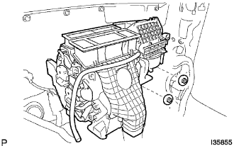
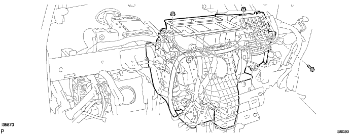
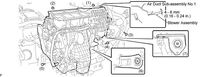
| 1. INSTALL BLOWER ASSEMBLY |
 |
Engage the claw to install the blower assembly.
| 2. INSTALL WIRING AIR INDICATOR HARNESS NO.2 SUB-ASSEMBLY |
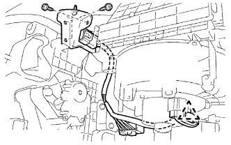 |
Install the wiring air indicator harness No.2 sub-assembly with the 3 screws.
Connect the connectors and clamp.
| 3. INSTALL AIR DUCT NO.2 |
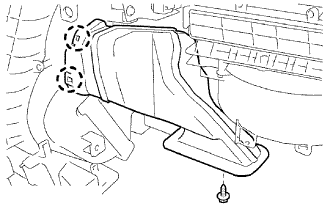 |
Install the air duct No.2 with the screw.
| 4. TEMPORARILY TIGHTEN AIR CONDITIONER UNIT ASSEMBLY |
 |
Temporarily tighten the air conditioner unit assembly with the 2 nuts.
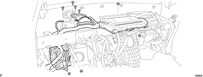
| 5. INSTALL INSTRUMENT PANEL REINFORCEMENT ASSEMBLY |
Install the instrument panel reinforcement with the 8 bolts.
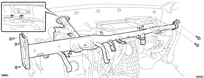
Temporarily tighten the air conditioner unit assembly with the 2 nuts and bolt.
Install the 4 bolts and 4 nuts.
Install the clamps.
Connect the connectors.
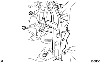
| 6. INSTALL INSTRUMENT PANEL BRACE NO.2 SUB-ASSEMBLY |
 |
Install the instrument panel brace No.2 sub-assembly with the 3 bolts and 2 nuts.
Install the clamps and connect the connectors.
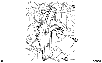
| 7. INSTALL INSTRUMENT PANEL BRACE NO.1 SUB-ASSEMBLY |
 |
Install the instrument panel brace No.1 sub-assembly with the 3 bolts and 2 nuts.
Install the clamps and connect the connectors.
| 8. INSTALL INSTRUMENT PANEL BRACKET NO.4 |
| 9. INSTALL AIR DUCT NO.1 SUB-ASSEMBLY |
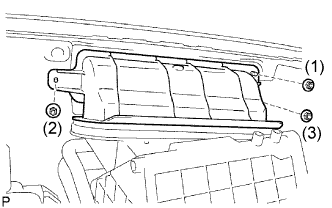 |
Install the air duct No.1 sub-assembly with the 3 nuts.
| 10. FULLY TIGHTEN AIR CONDITIONER UNIT ASSEMBLY |
Fully tighten the air conditioner unit assembly with the 3 bolts and 4 nuts.
| 11. INSTALL STEERING COLUMN ASSEMBLY (Manual Tilt Type) |
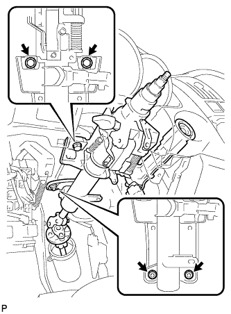 |
Install the steering column assembly with the 2 bolts and 2 nuts.
Connect the connectors to the steering column assembly.
| 12. INSTALL STEERING COLUMN ASSEMBLY (Power Tilt and Power Type) |
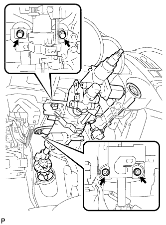 |
Install the steering column assembly with the 2 bolts and 2 nuts.
Connect the connectors to the steering column assembly.
Install the wire harness clamps to the steering column assembly.
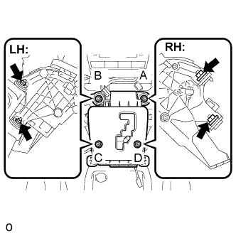
| 13. CONNECT STEERING INTERMEDIATE SHAFT SUB-ASSEMBLY (Manual Tilt Type) |
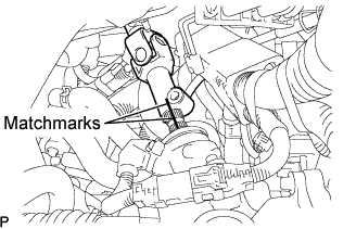 |
Align matchmarks on the steering intermediate shaft sub-assembly and the power steering link assembly.
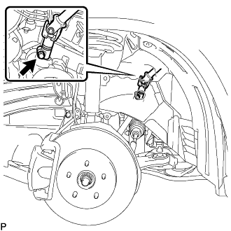 |
Install the bolt.
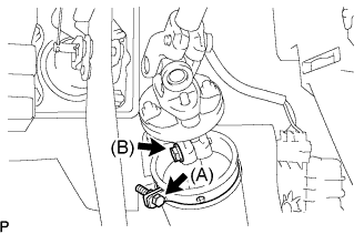 |
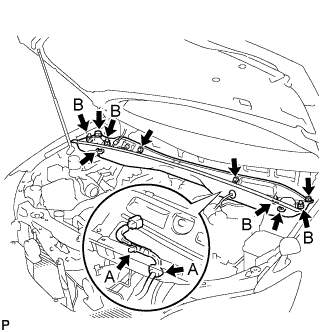
Tighten the bolt (B).
Install the clamp to the steering column hole shield and tighten the bolt (A).
| 14. CONNECT STEERING INTERMEDIATE SHAFT SUB-ASSEMBLY (Power Tilt and Power Type) |
|
Align matchmarks on the steering intermediate shaft sub-assembly and the power steering link assembly.
|
Install the bolt.
|
Tighten the bolt (B).
Install the clamp to the steering column hole shield and tighten the bolt (A).
| 15. INSTALL AIR DUCT NO.1 |
 |
Install the air duct No.1 with the bolt.
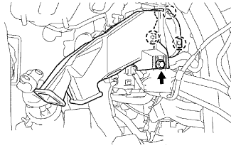
| 16. INSTALL HYBRID VEHICLE CONTROL ECU |
Install the hybrid vehicle control ECU with the 2 nuts.
Connect the 6 connectors to the hybrid vehicle control ECU.
Connect the 3 wire harness clamps.
| 17. INSTALL AIR CONDITIONER AMPLIFIER ASSEMBLY |
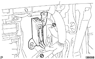 |
Install the air conditioner amplifier assembly with the 2 nuts.
| 18. INSTALL SHIFT LEVER |
 |
Install the floor shift assembly with the 4 nuts.
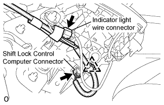 |
Install the pattern select switch connector, the shift lock control computer connector and the indicator light wire connector.
| 19. CONNECT TRANSMISSION CONTROL CABLE ASSEMBLY |
Connect the socket of the transmission control cable assembly to the shift lever assembly.
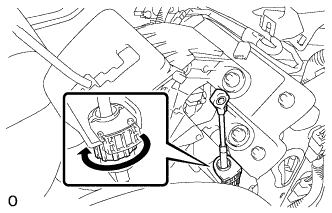 |
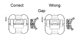
Turn the socket of the transmission control cable assembly clockwise and install the stopper cap.
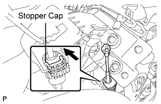 |
Push the stopper cap to the socket as shown in the illustration.
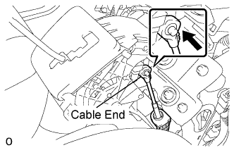 |
Connect the control cable end to the shift lever assembly.
| 20. INSPECT SHIFT LEVER POSITION |
Apply the parking brake.
Lock the wheels with chocks to secure the vehicle.
Put the vehicle into the READY-on state.
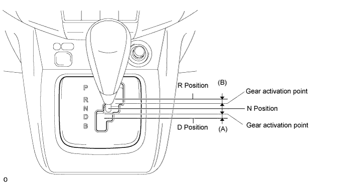
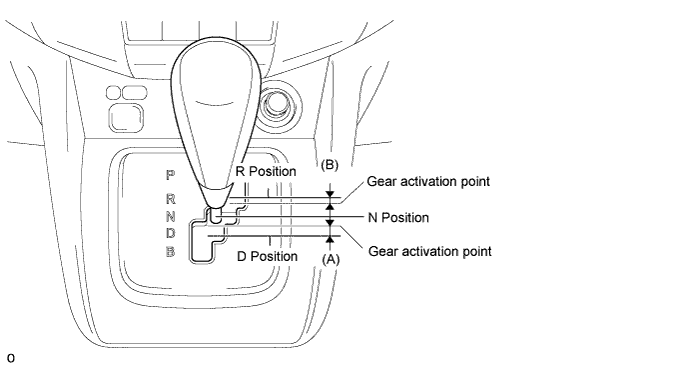
Move the shift lever to the D position and release the brake pedal.
Slowly move the shift lever to the N position and measure moving distance (A) of the shift lever from the original point to the gear activation point.
Move the shift lever to the R position and release the brake pedal.
Slowly move the shift lever to the N position and measure moving distance (B) of the shift lever from the original point to the vehicle activation point.
Check that moving distances (A) and (B) shown in the illustration are almost the same.
| 21. ADJUST SHIFT LEVER POSITION |
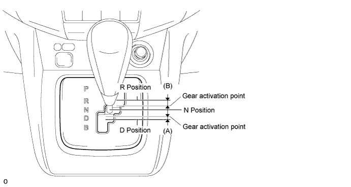
If moving distance (A) is shorter than (B) [*1]:
Move the shift lever to the N position.
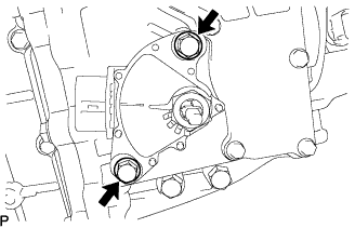 |
Loosen the 2 bolts.
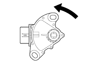 |
Slightly turn the park/neutral position switch counterclockwise.
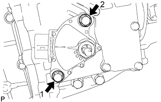 |
Tighten the 2 bolts in the order shown in the illustration.
Recheck the shift lever position.
If moving distance (B) is shorter than (A) [*2]:
Move the shift lever to the N position.
|
Loosen the 2 bolts.
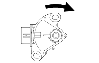 |
Slightly turn the park/neutral position switch clockwise.
|
Tighten the 2 bolts in the order shown in the illustration.
Recheck the shift lever position.
| 22. INSTALL AIR DUCT REAR NO.1 |
| 23. INSTALL AIR DUCT REAR NO.2 |
| 24. INSTALL INSTRUMENT PANEL ASSEMBLY |
| 25. INSTALL HEATER WATER INLET HOSE |
| 26. INSTALL HEATER WATER OUTLET HOSE |
| 27. INSTALL COOLER REFRIGERANT SUCTION HOSE NO.1 (LHD Type:) |
 |
Remove the attached vinyl tape from the hose.
Coat a new O-ring with compressor oil and install it to the hose.
Install the cooler refrigerant suction hose No.1 and piping clamp.
| 28. INSTALL COOLER REFRIGERANT SUCTION PIPE NO.1 (RHD Type:) |
|
Remove the attached vinyl tape from the hose.
Coat a new O-ring with compressor oil and install it to the hose.
Install the cooler refrigerant suction pipe No.1 and piping clamp.
| 29. INSTALL AIR CONDITIONING TUBE AND ACCESSORY ASSEMBLY |
Remove the attached vinyl tape from the hose.
Coat a new O-ring with compressor oil and install it to the pipe.
Install the air conditioning tube and accessory assembly and piping clamp.
| 30. INSTALL COWL TOP PANEL OUTER SUB-ASSEMBLY |
Remove the 4 shock absorber nuts.
 |
Install the 4 bolts, 2 nuts and cowl top panel sub-assembly.
Install the 4 shock absorber nuts (B).
Install the wire harness clamp and grommet (A).
| 31. INSTALL WINDSHIELD WIPER LINK ASSEMBLY |
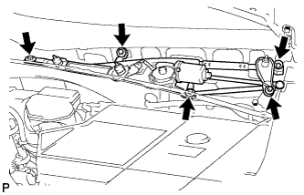 |
Install the windshield wiper motor and link assembly with the 5 bolts.
Connect the connector.
| 32. INSTALL COWL TOP VENTILATOR LOUVER SUB-ASSEMBLY |
| 33. INSTALL FRONT WIPER ARM AND BLADE ASSEMBLY LH |
 |
Operate the front wiper, and stop the front wiper motor at the automatic stop position.
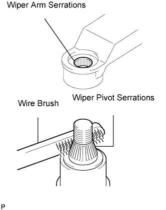
Clean the wiper arm serrations.
Clean the wiper pivot serrations with a wire brush (when reinstalling).
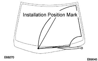 |
Install the front wiper arm and blade assembly LH with the nut at the position as shown in the illustration.
| 34. INSTALL FRONT WIPER ARM AND BLADE ASSEMBLY RH |
|
Clean the wiper arm serrations.
Clean the wiper pivot serrations with a wire brush (when reinstalling).
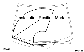 |
Install the front wiper arm and blade assembly RH with the 2 nuts at the position as shown in the illustration.
Operate the front wipers while spraying water or washer fluid on the windshield.
Make sure that the wipers function properly and there is no interference with the vehicle body.
| 35. ADD ENGINE COOLANT |
Tighten the lower drain plug of the radiator.
Loosen the upper drain plug of the radiator.
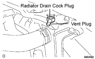 |
Install a vinyl tube to the vent plug located on the upper drain plug.
Fill the radiator with engine coolant until the vinyl tube is filled with the coolant.
Tighten the upper drain plug.
Install the radiator cap securely.
Fill the radiator reservoir tank with coolant.
Warm up the engine.
Stop the engine and wait until the coolant cools down.
Remove the radiator cap and check the coolant level inside the radiator.
If the coolant level is below the full level, perform the steps from (a) through (j) and repeat the operation until the coolant level stays the full level.
Recheck the coolant level inside the radiator reservoir tank. If it is below the full level, add the coolant.
| 36. CONNECT CABLE TO NEGATIVE BATTERY TERMINAL |
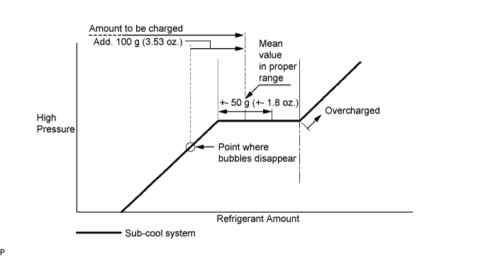
| 37. CHARGE WITH REFRIGERANT |
Perform vacuum purging using a vacuum pump.
Charge with refrigerant HFC-134a (R134a).
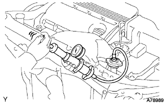
| 38. WARM UP COMPRESSOR |
Keep the A/C switch on for at least 2 minutes to warm up the compressor.
| 39. CHECK FOR ENGINE COOLANT LEAKS |
 |
Fill the radiator with coolant and attach a radiator cap tester.
Warm up the engine.
Using a radiator cap tester, increase the pressure inside the radiator to 118 kPa (1.2 kgf*cm, 17 psi), and check that the pressure does not drop.
If the pressure drops, check the hoses, radiator and water pump for leaks. If no external leaks are found, check the heater core, cylinder block and cylinder head.
| 40. CHECK FOR LEAKAGE OF REFRIGERANT |
After recharging refrigerant gas, check for leakage of refrigerant gas using a halogen leak detector.
Carry out the test under the following conditions:
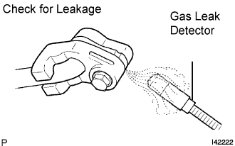 |
Using a gas leak detector, check for leakage of the refrigerant line.
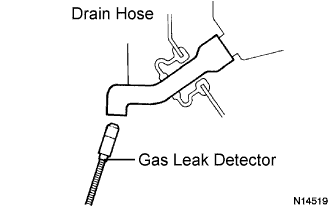 |
Bring the gas leak detector close to the drain hose with the detector's power off.
If a gas leak is not detected on the drain hose, remove the blower motor control from the cooling unit. Insert the gas leak detector sensor into the unit and perform the test.
Disconnect the pressure switch connector and leave it for approximately 20 minutes. Bring the gas leak detector close to the pressure switch and perform the test.
| 41. REMOVE PERFORM INITIALIZATION |
