ELECTRIC INVERTER COMPRESSOR > INSTALLATION |
| 1. ADJUST COMPRESSOR OIL |
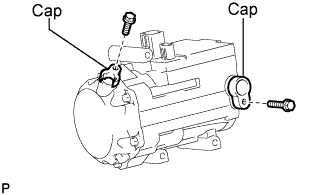 |
When replacing the electric inverter compressor with a new one, gradually discharge the refrigerant gas from the cap, and drain the following amount of oil from the new electric inverter compressor before installation.
| 2. INSTALL SERVICE VALVE (LHD Type:) |
Apply sufficient compressor oil (ND-OIL 11) to a new O-ring and the fitting surface of the electric inverter compressor.
Install the O-ring onto the service valve.
 |
Install the service valve No.1 with the bolt.
| 3. INSTALL ELECTRIC INVERTER COMPRESSOR |
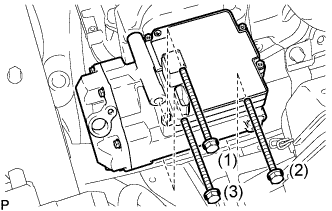 |
Install the electric inverter compressor with the 3 bolts.
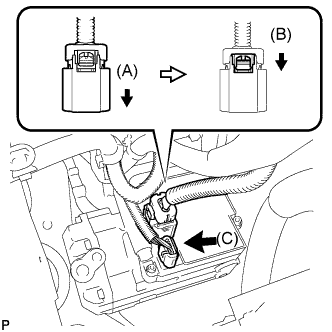 |
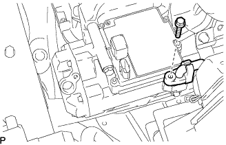
Connect the connector (A).
Lock the green-colored lock (B).
Connect the connector (C).
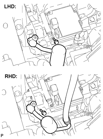
| 4. INSTALL COOLER REFRIGERANT SUCTION HOSE NO.1 (LHD Type:) |
Remove the attached vinyl tape from the hose.
Apply sufficient compressor oil (ND-OIL 11 or equivalent) to a new O-ring and the fitting surface of the electric inverter compressor.
Install the O-ring onto the cooler refrigerant suction hose No.1.
 |
Install the cooler refrigerant suction hose No.1 onto the electric inverter compressor with the bolt.
| 5. INSTALL COOLER REFRIGERANT SUCTION HOSE NO.1 (RHD Type:) |
Remove the attached vinyl tape from the hose.
Apply sufficient compressor oil (ND-OIL 11 or equivalent) to a new O-ring and the fitting surface of the electric inverter compressor.
Install the O-ring onto the cooler refrigerant suction hose No.1.
 |
Install the cooler refrigerant suction hose No.1 onto the electric inverter compressor with the bolt.
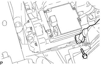
| 6. INSTALL COOLER REFRIGERANT DISCHARGE HOSE NO.1 |
Remove the attached vinyl tape from the hose.
Apply sufficient compressor oil (ND-OIL 11 or equivalent) to a new O-ring and the fitting surface of the electric inverter compressor.
Install the O-ring onto the cooler refrigerant discharge hose No.1.
 |
Install the cooler refrigerant discharge hose No.1 onto the electric inverter compressor with the bolt.
| 7. INSTALL BATTERY |
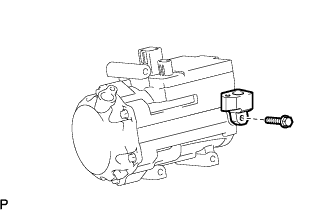
| 8. INSTALL POWER STEERING ECU BRACKET |
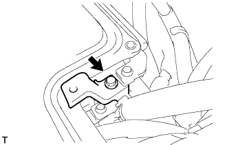 |
Install the power steering ECU bracket with the bolt to the w/ converter inverter assembly.
| 9. INSTALL INVERTER RESERVE TANK SUB-ASSEMBLY |
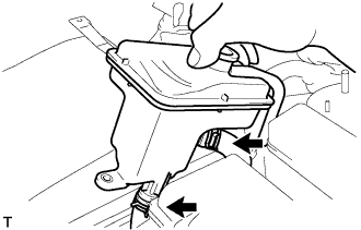 |
Connect the 2 water hoses with the 2 clamps to the inverter reserve tank sub-assembly.
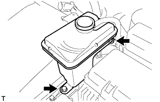 |
Install the inverter reserve tank with the 2 bolts to the w/ converter inverter assembly.
| 10. CONNECT CABLE TO NEGATIVE BATTERY TERMINAL |
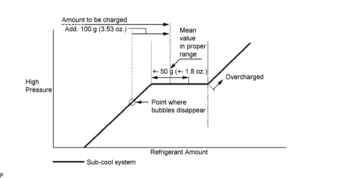
| 11. CHARGE WITH REFRIGERANT |
Perform vacuum purging using a vacuum pump.
Charge with refrigerant HFC-134a (R134a).
| 12. WARM UP COMPRESSOR |
Keep the A/C switch on for at least 2 minutes to warm up the compressor.
| 13. CHECK FOR LEAKAGE OF REFRIGERANT |
After recharging refrigerant gas, check for leakage of refrigerant gas using a halogen leak detector.
Carry out the test under the following conditions:
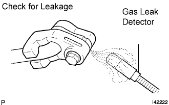 |
Using a gas leak detector, check for leakage of the refrigerant line.
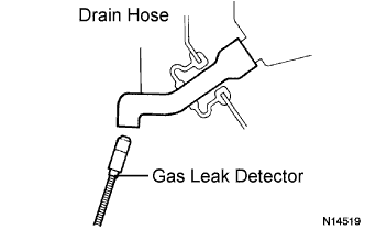 |
Bring the gas leak detector close to the drain hose with the detector's power off.
If a gas leak is not detected on the drain hose, remove the blower motor control from the cooling unit. Insert the gas leak detector sensor into the unit and perform the test.
Disconnect the pressure switch connector and leave it for approximately 20 minutes. Bring the gas leak detector close to the pressure switch and perform the test.
| 14. PERFORM INITIALIZATION |
