ELECTRIC INVERTER COMPRESSOR > REMOVAL |
| 1. DISCHARGE REFRIGERANT FROM REFRIGERATION SYSTEM |
Turn the A/C switch on.
Operate the A/C with the setting temperature at 25°C (77°F) and the blower level at LO for 10 minutes to circulate the refrigerant and collect compressor oil remaining in each component into the cooler compressor as much as possible.
Turn the ignition switch OFF.
Using SST, let the refrigerant gas out.
| 2. DISCONNECT CABLE FROM NEGATIVE BATTERY TERMINAL |
| 3. REMOVE SERVICE PLUG GRIP |
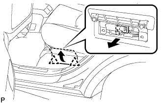 |
Remove the 2 clips, then open the battery service hole cover.
Wear insulation glove, and remove the service plug grip, after sliding up the lever of the service plug grip.
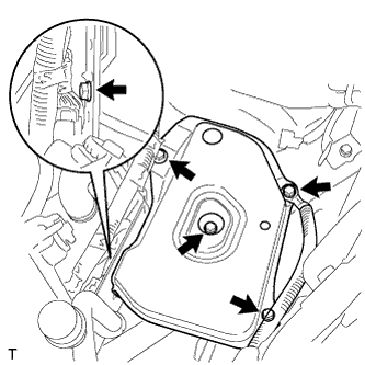
| 4. SEPARATE INVERTER RESERVE TANK SUB-ASSEMBLY |
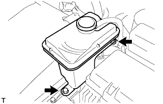 |
Remove the 2 bolts and inverter reserve tank sub-assembly.
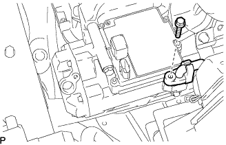
| 5. DISCONNECT POWER STEERING ECU BRACKET |
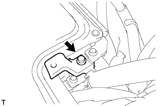 |
Remove the bolt, and disconnect the power steering ECU bracket.
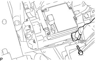
| 6. REMOVE INVERTER COVER |
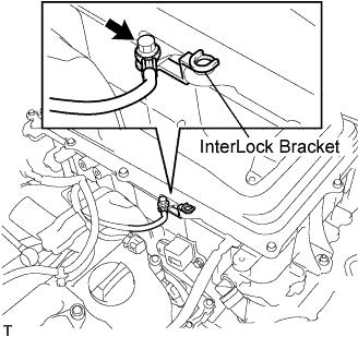 |
Remove the bolt and interlock bracket.
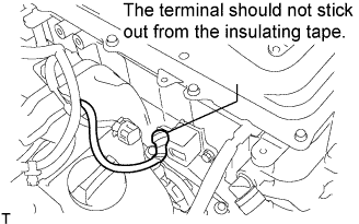 |
Insulate the removed terminal with insulating tape.
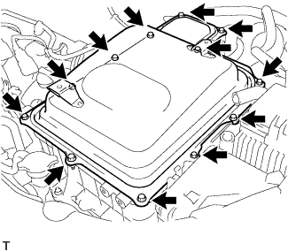 |
Remove the 12 bolts and inverter cover.
| 7. VERIFY THAT VOLTAGE OF W/ CONVERTER ASSEMBLY IS 0V |
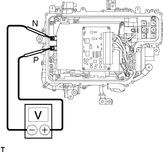 |
Using the voltmeter, measure the voltage between the terminals of the 2 phase connectors (N-P).
| 8. INSTALL INVERTER COVER |
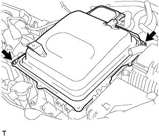 |
Temporarily install the inverter cover with the 2 bolts to prevent any foreign objects or waterdrops from entering the w/ converter inverter assembly.
| 9. REMOVE BATTERY |
Remove the bolt and battery clamp.
Remove the battery and battery tray.
| 10. REMOVE BATTERY CARRIER SUB-ASSEMBLY |
 |
Remove the 5 bolts and battery carrier.
| 11. DISCONNECT COOLER REFRIGERANT DISCHARGE HOSE NO.1 |
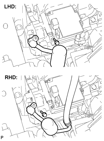 |
Remove the bolt and disconnect the cooler refrigerant discharge hose No.1 from the electric inverter compressor.
Remove the O-ring from the cooler refrigerant discharge hose No.1.
| 12. DISCONNECT COOLER REFRIGERANT SUCTION HOSE NO.1 (LHD Type:) |
 |
Remove the bolt and disconnect the cooler refrigerant suction hose No.1 from the electric inverter compressor.
Remove the O-ring from the cooler refrigerant suction hose No.1.
| 13. REMOVE COOLER REFRIGERANT SUCTION HOSE NO.1 (RHD Type:) |
 |
Remove the bolt and disconnect the cooler refrigerant suction hose No.1 from the electric inverter compressor.
Remove the O-ring from the cooler refrigerant suction hose No.1.
| 14. REMOVE ELECTRIC INVERTER COMPRESSOR |
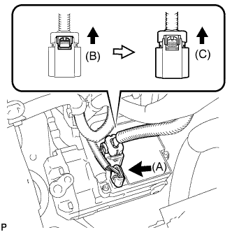 |
Disconnect the connector (A).
Release the green-colored lock (B).
Disconnect the connector (C).
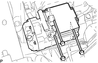 |
Remove the 3 bolts and electric inverter compressor.
| 15. REMOVE SERVICE VALVE (LHD Type:) |
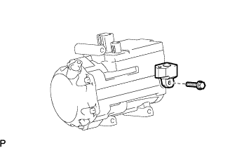 |
Remove the bolt and service valve.
Remove the O-ring from the service valve.
