CONDENSER > INSTALLATION

for Preparation Click here


1. INSTALL COOLER CONDENSER ASSEMBLY


    E108158
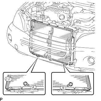
  1. Install the cooler condenser assembly with the 2 screws.

    Torque:
    3.9 N*m{ 40 kgf*cm , 35 in.*lbf }


2. INSTALL RADIATOR SUPPORT UPPER RH SUB-ASSEMBLY


    E111243E03
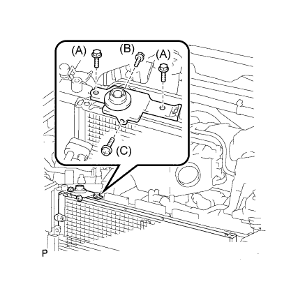
  1. Install the radiator support upper RH sub-assembly with the 4 bolts.

    Torque:
    Bolt A:
    5.0 N*m{ 51 kgf*cm , 44 in.*lbf }
    Bolt B:
    7.0 N*m{ 71 kgf*cm , 62 in.*lbf }
    Bolt C:
    3.9 N*m{ 40 kgf*cm , 35 in.*lbf }


3. INSTALL RADIATOR SUPPORT UPPER LH SUB-ASSEMBLY


    E108506E02
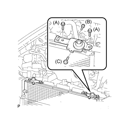
  1. Install the radiator support upper LH sub-assembly with the 4 bolts.

    Torque:
    Bolt A:
    5.0 N*m{ 51 kgf*cm , 44 in.*lbf }
    Bolt B:
    7.0 N*m{ 71 kgf*cm , 62 in.*lbf }
    Bolt C:
    3.9 N*m{ 40 kgf*cm , 35 in.*lbf }


4. INSTALL RADIATOR SUPPORT UPPER SUB-ASSEMBLY


    E108157
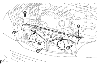
  1. Install the radiator support upper sub-assembly with the 5 bolts and nut.

    Torque:
    Bolt:
    7.0 N*m{ 71 kgf*cm , 62 in.*lbf }
    Nut:
    8.0 N*m{ 82 kgf*cm , 71 in.*lbf }

  1. Connect the connectors.

  1. Install the cap.


    E110833
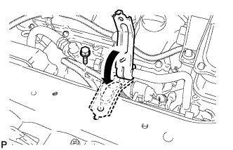
  1. Install the bracket with the bolt.

    Torque:
    9.8 N*m{ 100 kgf*cm , 87 in.*lbf }


5. INSTALL AIR CONDITIONING TUBE AND ACCESSORY ASSEMBLY
  1. Remove the attached vinyl tape from the tube and connecting part of the cooler condenser assembly.

  1. Sufficiently apply compressor oil to a new O-ring and fitting surface of the pipe joint.

    Compressor oil:
    ND-OIL 11 or equivalent

    NOTICE:
    1. Do not use any compressor oil other than ND-OIL 11 or equivalent.
    2. If any compressor oil other than ND-OIL 11 or equivalent is used, compressor motor insulation performance may decrease, resulting in leakage of electric power.

  1. Install the O-ring on the air conditioning tube and accessory assembly.


    E108155
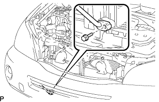
  1. Connect the air conditioning tube and accessory assembly to the cooler condenser assembly with the bolt.

    Torque:
    9.8 N*m{ 100 kgf*cm , 87 in.*lbf }


6. INSTALL COOLER REFRIGERANT DISCHARGE HOSE NO.1
  1. Remove the attached vinyl tape from the tube and connecting part of the cooler condenser assembly.

  1. Sufficiently apply compressor oil to a new O-ring and fitting surface of the pipe joint.

    Compressor oil:
    ND-OIL 11 or equivalent

    NOTICE:
    1. Do not use any compressor oil other than ND-OIL 11 or equivalent.
    2. If any compressor oil other than ND-OIL 11 or equivalent is used, compressor motor insulation performance may decrease, resulting in leakage of electric power.


    E108154
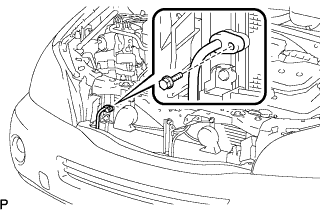
  1. Install the O-ring to the cooler refrigerant discharge hose No.1.

  1. Connect the cooler refrigerant discharge hose No.1 on the cooler condenser assembly with the bolt.

    Torque:
    9.8 N*m{ 100 kgf*cm , 87 in.*lbf }


7. INSTALL FRONT BUMPER STAY CENTER


8. INSTALL AIR CLEANER CAP W/ INLET


9. INSTALL COOL AIR INTAKE DUCT SEAL


10. INSTALL ENGINE ROOM SIDE LH COVER


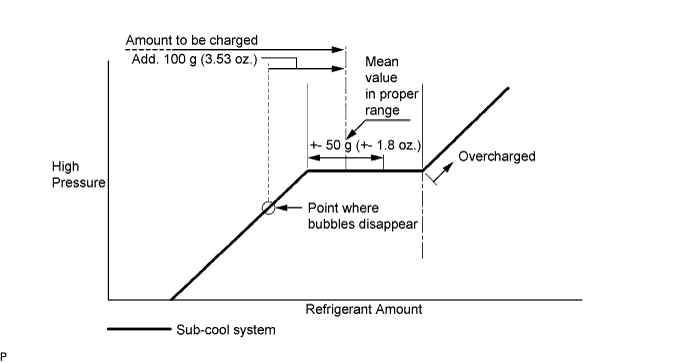
11. CHARGE WITH REFRIGERANT
  1. Perform vacuum purging using a vacuum pump.


  1. Charge with refrigerant HFC-134a (R134a).


    I030082E03

    Standard:
    550 to 650 g (19.4 to 22.9 oz.)

    SST
    07110-58060   (07117-58060, 07117-58070, 07117-58080, 07117-58090, 07117-78050, 07117-88060, 07117-88070, 07117-88080)

    NOTICE:
    1. Do not turn the A/C on before charging with refrigerant because the compressor will overheat as a result of the cooler compressor not working properly without refrigerant.
    2. Approximately 100 g (3.53 oz.) of refrigerant may need to be charged after bubbles disappear.
      The refrigerant amount should be checked by quantity, and not with the sight glass.
    3. Avoid using the gauge manifold set that had been used for vehicles with conventional compressor oil (ND-OIL8 or equivalent) as much as possible. This will cause compressor oil remaining in the manifold to enter the vehicle, resulting in insulation performance deterioration. A gauge manifold set that had been used 3 times or less can be reused if an appropriate one is not available.

    HINT:
    Prepare a service can to recharge refrigerant if using the refrigerant gas collected with the freon collection/recycling device because the collective rate of the device is approximately 90%.


12. WARM UP COMPRESSOR
  1. Keep the A/C switch on for at least 2 minutes to warm up the compressor.

    NOTICE:
    Be sure to warm up the compressor when turning the A/C on after removing and installing the cooler refrigerant lines (including the compressor), to prevent damage to the compressor.


13. CHECK FOR LEAKAGE OF REFRIGERANT
  1. After recharging refrigerant gas, check for leakage of refrigerant gas using a halogen leak detector.

  1. Carry out the test under the following conditions:

    1. IG OFF
    2. Secure good ventilation (the gas leak detector may react to volatile gases which are not refrigerant, such as evaporated gasoline and exhaust gas).
    3. Repeat the test 2 or 3 times.
    4. Make sure that there is some refrigerant remaining in the refrigeration system.
      When the compressor is off: approx. 392 to 588 kPa (4 to 6 kgf/cm2, 57 to 85 psi)


    I042222E02
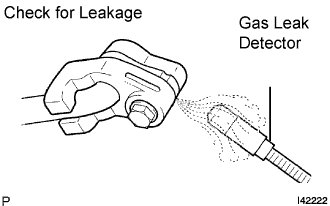
  1. Using a gas leak detector, check for leakage of the refrigerant line.


    N014519E01
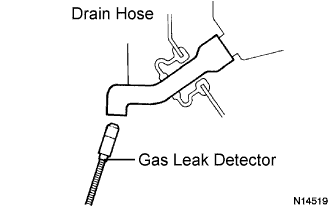
  1. Bring the gas leak detector close to the drain hose with the detector's power off.

    HINT:
    1. After the blower motor has stopped, let the cooling unit stand for more than 15 minutes.
    2. Bring the gas leak detector sensor under the drain hose.
    3. When bringing the gas leak detector close to the drain hose, make sure that the gas leak detector does not react to volatile gases.
      If such reaction is unavoidable, the vehicle must be lifted up.

  1. If a gas leak is not detected on the drain hose, remove the blower motor control from the cooling unit. Insert the gas leak detector sensor into the unit and perform the test.

  1. Disconnect the pressure switch connector and leave it for approximately 20 minutes. Bring the gas leak detector close to the pressure switch and perform the test.