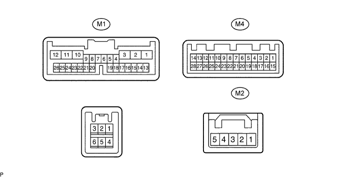
Symbols (Terminal No.)
| Wiring Color
| Terminal Description
| Condition
| Specification
|
GND (M4-3 ) - Body ground
| W-B - Body ground
| Ground
| Always
| Below 1 V
|
MCI+ (M4-4) - GND (M4-3)
| G - W-B
| Microphone voice signal
| See "microphone check" (Click here)
| -
|
MCI- (M4-5) - Body ground
| R - Body ground
| Microphone voice signal
| See "microphone check" (Click here)
| -
|
MACC (M4-6) - GND (M4-3)
| Y - W-B
| Microphone AMP power supply
| Turn ignition switch OFF → ON
| Below 1 V → 5 V
|
TX+ (M4-13) - GND (M4-3)
| P - W-B
| AVC-LAN communication signal
| Turn ignition switch to ACC
| 2 to 3 V
|
TX- (M4-14) - GND (M4-3)
| L - W-B
| AVC-LAN communication signal
| Turn ignition switch to ACC
| 2 to 3 V
|
SGND (M4-17) - Body ground
| Shielded - Body ground
| Shielded ground
| Always
| Below 1 V
|
MCO+ (M4-18) - GND (M4-3)
| BR - W-B
| Microphone voice signal
| See "microphone check" (Click here)
| -
|
MCO- (M4-19) - GND (M4-3)
| Y - W-B
| Microphone voice signal
| See "microphone check" (Click here)
| -
|
SLD (M4-20) - Body ground
| Shielded - Body ground
| Shielded ground
| Always
| Below 1 V
|
VOI+ (M4-21) - GND (M4-3)
| R - W-B
| Telephone voice signal (bluetooth)
| See "microphone check" (Click here)
| -
|
IVO- (M4-22) - GND (M4-3)
| G - W-B
| Telephone voice signal (bluetooth)
| See "microphone check" (Click here)
| -
|
VR (M4-23) - GND (M4-3)
| Y - W-B
| Video return signal
| Turn ignition switch OFF
| Below 1 V
|
R (M4-24) - GND (M4-3)
| L - W-B
| Display signal (red)
| Navigation display is on
| -
|
G (M4-25) - GND (M4-3)
| W - W-B
| Display signal (green)
| Navigation display is on
| -
|
B (M4-26) - GND (M4-3)
| R - W-B
| Display signal (blue)
| Navigation display is on
| -
|
SYNC (M4-27) - GND (M4-3)
| BR - W-B
| Display signal (synchronize)
| Navigation display is on
| -
|
VG (M4-28) - GND (M4-3)
| B-W - W-B
| Shielded ground
| Always
| Below 1 V
|
ILL+ (M1-1) - GND (M4-3)
| G - W-B
| Illumination signal
| Turn ignition switch OFF → ON
| Below 1 V → 10 to 14 V
|
ILL- (M1-2) - Body ground
| W - Body ground
| Illumination signal
| Turn ignition switch OFF → ON
| Below 1 V → 10 to 14 V
|
GND (M1-3) - Body ground
| W-B - Body ground
| Ground
| Always
| Below 1 V
|
TX1+ (M1-4) - GND (M4-3)
| Y - W-B
| AVC-LAN communication signal
| Turn ignition switch to ACC
| 2 to 3 V
|
TX1- (M1-5) - GND (M4-3)
| BR - W-B
| AVC-LAN communication signal
| Turn ignition switch to ACC
| 2 to 3 V
|
TC (M1-7) - GND (M4-3)
| P - W-B
| Diagnosis ON signal
| Turn ignition switch to ON
| 9 to 14 V
|
F (M1-8) - GND (M4-3)
| V - W-B
| Hazard signal
| Turn hazard switch OFF → ON
| Below 1 V → 10 to 14 V or below 1 V
|
IG (M1-10) - GND (M4-3)
| LG - W-B
| Ignition (ON)
| Turn ignition switch OFF → ON
| Below 1 V → 10 to 14 V
|
ACC (M1-11) - GND (M4-3)
| GR - W-B
| Accessory (ON)
| Turn ignition switch OFF → ACC or ON
| Below 1 V → 10 to 14 V
|
+B1 (M1-12) - GND (M4-3)
| G - W-B
| Battery
| Always
| 10 to 14 V
|
PKB (M1-16) - GND (M4-3)
| W - W-B
| Parking brake signal
| Turn parking brake switch ON → OFF
| Below 1 V → 10 to 14 V
|
ADIM (M1-17) - GND (M4-3)
| SB - W-B
| Illumination (auto dimmer) signal
| Ignition switch ON, light control switch TAIL or ON and automatic light control sensor covered by hand
| Above 9 V
|
TX3+ (M1-18) - GND (M4-3)
| R - W-B
| AVC-LAN communication signal
| Turn ignition switch to ON
| 2 to 3 V
|
TX3- (M1-19) - GND (M4-3)
| B - W-B
| AVC-LAN communication signal
| Turn ignition switch to ON
| 2 to 3 V
|
PBEW (M1-21) - GND (M4-3)
| O - W-B
| Passenger (front) seat belt warning signal
| Turn ignition switch to ON, front passenger seat and front seat buckle switch ON (Belt unfastened) → OFF (Belt fastened)
| 10 to 14 V → Below 1 V
|
SPD (M1-25) - GND (M4-3)
| SB - W-B
| Speed signal from combination meter
| See "Vehicle Signal Check Mode" (Click here)
| -
|
HSY (M2-1) - GND (M1-3)
| P - W-B
| Theft deterrent indicator signal
| Insert ignition key → Remove key from ignition key cylinder
| Below 1 V → Pulse generation
|
ILL- (M2-5) - Body ground
| W - Body ground
| Illumination signal
| Turn ignition switch OFF → ON
| Below 1 V → 10 to 14 V
|
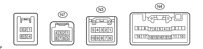
Symbols (Terminal No.)
| Wiring Color
| Terminal Description
| Condition
| Specification
|
VR (N3-1) - GND1 (N4-17)
| Y - W-B
| Video return signal
| Turn ignition switch OFF
| Below 1 V
|
R (N3-2) - GND1 (N4-17)
| G - W-B
| Display signal (red)
| Navigation display is on
| -
|
B (N3-3) - GND1 (N4-17)
| R - W-B
| Display signal (blue)
| Navigation display is on
| -
|
TX+ (N3-5) - GND1 (N4-17)
| R - W-B
| AVC-LAN communication signal
| Turn ignition switch to ACC
| 2 to 3 V
|
VG (N3-6) - Body ground
| Shielded - Body ground
| Shielded ground
| Always
| Below 1 V
|
G (N3-7) - GND1 (N4-17)
| W - W-B
| Display signal (green)
| Navigation display is on
| -
|
SYNC (N3-8) - GND1 (N4-17)
| B - W-B
| Display signal (synchronize)
| Navigation display is on
| -
|
TX- (N3-10) - GND1 (N4-17)
| Y - W-B
| AVC-LAN communication signal
| Turn ignition switch to ACC
| 2 to 3 V
|
AUI+ (N4-1) - GND1 (N4-17)
| Y - W-B
| Sound signal (input)
| Audio system is playing
| -
|
AUO+ (N4-2) - GND1 (N4-17) (*1)
| BR - W-B
| Sound signal (output)
| Audio system is playing
| -
|
AUO+ (N4-2) - GND1 (N4-17) (*2)
| B - W-B
| Sound signal (output)
| Audio system is playing
| -
|
SPD (N4-5) - GND1 (N4-17)
| SB - W-B
| Speed signal from combination meter
| See "Vehicle Sensors" mode (Click here)
| -
|
CMP- (N4-6) - GND1 (N4-17)
| Y - W-B
| RDS-TMC signal (input)
| See "RDS-TMC Information" (Click here)
| -
|
CMP+ (N4-7) - GND1 (N4-17)
| BR - W-B
| RDS-TMC signal (input)
| See "RDS-TMC Information" (Click here)
| -
|
+B (N4-9) - GND1 (N4-17)
| L - W-B
| Battery
| Always
| 10 to 14 V
|
AUI- (N4-10) - GND1 (N4-17)
| LG - W-B
| Sound signal (input)
| Audio system is playing
| -
|
AUO- (N4-11) - GND1 (N4-17) (*1)
| R-Y - W-B
| Sound signal (output)
| Audio system is playing
| -
|
AUO- (N4-11) - GND1 (N4-17) (*2)
| Y - W-B
| Sound signal (output)
| Audio system is playing
| -
|
VOI+ (N4-12) - GND1 (N4-17)
| R - W-B
| Telephone voice signal (bluetooth)
| See "microphone check" (Click here)
| -
|
VOI- (N4-13) - GND1 (N4-17)
| G - W-B
| Telephone voice signal (bluetooth)
| See "microphone check" (Click here)
| -
|
REV (N4-14) - GND1 (N4-17)
| R - W-B
| Reverse signal from combination meter
| See "Vehicle Sensors" mode (Click here)
| -
|
MUT2 (N4-15) - GND1 (N4-17)
| V - W-B
| Mute signal
| Audio system is playing → Changing
| Above 3.5 V → Below 1 V
|
RSG (N4-16) - Body ground
| Shielded - Body ground
| Shielded ground
| Always
| Below 1 V
|
GND1 (N4-17) - Body ground
| W-B - Body ground
| Ground
| Always
| Below 1 V
|
ACC (N4-18) - GND1 (N4-17)
| P - W-B
| Accessory (ON)
| Turn ignition switch OFF → ACC or ON
| Below 1 V → 10 to 14 V
|
MIC+ (N7-3) - GND1 (N4-17)
| BR - W-B
| Microphone voice signal
| See "microphone check" (Click here)
| -
|
MIC- (N7-5) - GND1 (N4-17)
| Y - W-B
| Microphone voice signal
| See "microphone check" (Click here)
| -
|
SNSE (N7-7) - Body ground
| W-B - Body ground
| Microphone connection detection signal
| Always
| Below 1 V
|