NAVIGATION SYSTEM > SYSTEM DESCRIPTION |
| Navigation system outline |
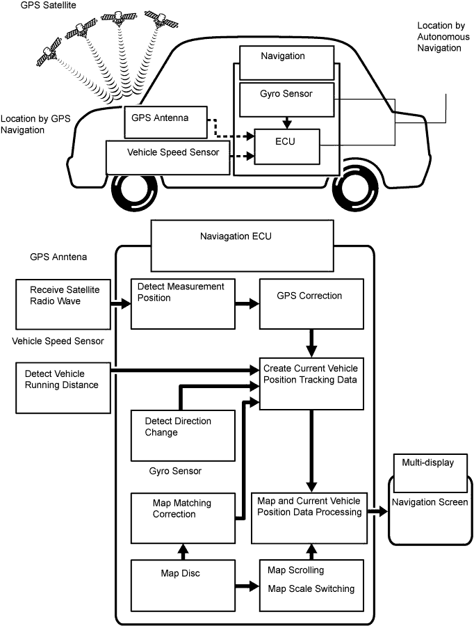
Vehicle position tracking methods
It is essential that the navigation system correctly tracks the current vehicle position and displays it on the map. There are 2 methods to track the current vehicle position: autonomous (dead reckoning) and GPS* (satellite) navigation. Both navigation methods are used in conjunction with each other.
*GPS (Global Positioning System)
| Operation | Description |
| Vehicle Position Calculation | The navigation ECU calculates the current vehicle position (direction and current position) using the direction deviation signal from the gyro sensor and the running distance signal from the vehicle speed sensor and creates the driving route. |
| Map Display Processing | The navigation ECU displays the vehicle track on the map by processing the vehicle position data, vehicle running track, and map data from the map disc. |
| Map Matching | The map data from the map disc is compared to the vehicle position and running track data. Then, the vehicle position is matched with the nearest road. |
| GPS Correction | The vehicle position is matched to the position measured by GPS. Then, the measurement position data from the GPS unit is compared with the vehicle position and running track data. If the position is widely different, the GPS measurement position is used. |
| Distance Correction | The running distance signal from the vehicle speed sensor includes the error caused by tire wear and slippage between the tires and road surface. Distance correction is performed to account for this. The navigation ECU automatically offsets the running distance signal to make up for the difference between it and the distance data of the map. The offset is automatically updated. |
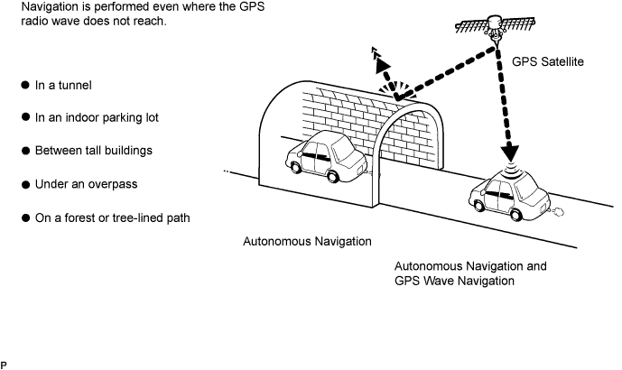
Autonomous navigation
This method determines the relative vehicle position based on the running track determined by the gyro and vehicle speed sensors located in the navigation ECU.
Gyro sensor
Calculates the direction by detecting angular velocity. It is located in the navigation ECU.
Vehicle speed sensor
Used to calculate the vehicle running distance.
GPS navigation (Satellite navigation)
This method detects the absolute vehicle position using radio waves from a GPS satellite.
* GPS satellites were launched by the U.S. Department of Defence for military purposes.
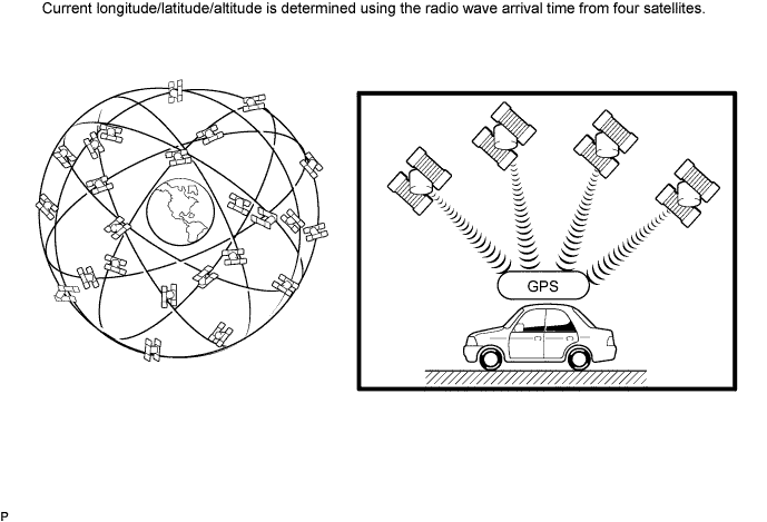
| Number of satellites | Measurement | Description |
| 2 or less | Measurement impossible | Vehicle position cannot be obtained because the number of satellites is not enough. |
| 3 | 2-dimensional measurement is possible | Vehicle position is obtained based on the current longitude and latitude. (This is less precise than 3-dimensional measurement.) |
| 4 | 3-dimensional measurement is possible | Vehicle position is obtained based on the current longitude, latitude and altitude. |
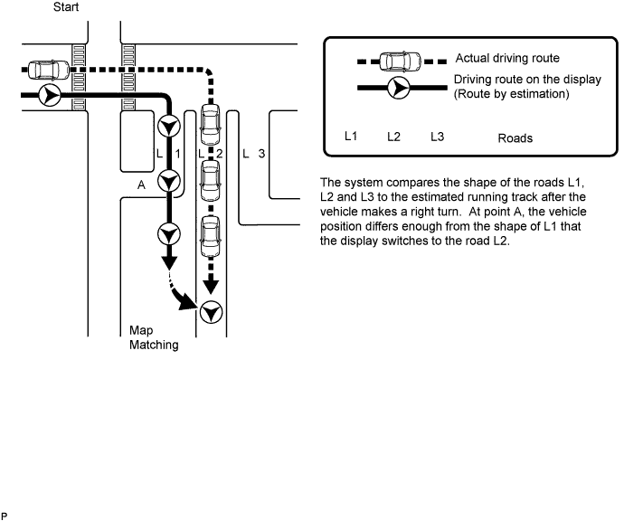
Map matching
The current driving route is calculated by autonomous navigation (according to the gyro sensor and vehicle speed sensor) and GPS navigation. This information is then compared with possible road shapes from the map data in the map disc and the vehicle position is set onto the most appropriate road.
| DVD (Digital Versatile Disc) player outline (for navigation map) |
The navigation ECU uses a laser pickup to read the digital signals recorded on a DVD.
| Multi-display outline |
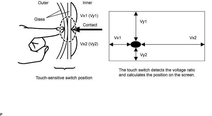
Touch switch
Touch switches are touch-sensitive (interactive) switches operated by touching the screen. When a switch is pressed, the outer glass bends in to contact the inner glass at the pressed position. By doing this, the voltage ratio is measured and the pressed position is detected.
| AVC-LAN Description |
What is AVC-LAN?
AVC-LAN, an abbreviation for "Audio Visual Communication Local Area Network", is a united standard developed by the manufacturers in affiliation with Toyota Motor Corporation. This standard pertains to audio and visual signals as well as switch and communication signals.
Purpose:
Recently, car audio systems have rapidly developed and the functions have vastly changed. The conventional car audio system is being integrated with multi-media interfaces similar to those in navigation systems. At the same time, customers are demanding higher quality from their audio systems. This is merely an overview of the standardization background. The specific purposes are as follows.
To solve sound problems, etc. caused by using components of different manufacturers through signal standardization.
To allow each manufacturer to concentrate on developing products they do best. From this, reasonably priced products can be produced.
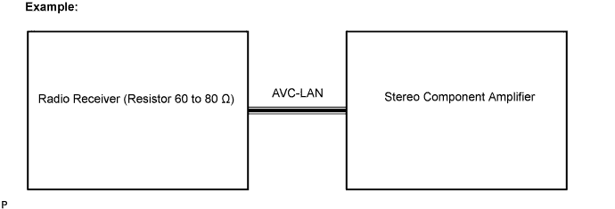
| Communication system outline |
Components of the navigation system communicate with each other via the AVC-LAN.
The radio receiver has enough resistance (60 to 80 Ω) necessary for communication.
If a short circuit or open circuit occurs in the AVC-LAN, communication is interrupted and the navigation system will stop functioning.
| Diagnostic function outline |
The audio system has a diagnostic function (the result is indicated on the master unit).
A 3-digit hexadecimal component code (physical address) is allocated to each component on the AVC-LAN. Using this code, the component in the diagnostic function can be displayed.
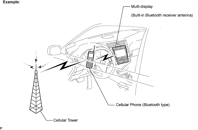
| Bluetooth outline |
Bluetooth is a new wireless connection technology that uses the 2.4 GHz frequency band. This makes it possible to connect a cellular phone (Bluetooth compatible phone *1) to the multi-display (the Bluetooth system is built in), and use a hands-free function with the cellular phone either in a pocket or bag. As a result, it is not necessary to use a connector attached directly to the cellular phone.
*1: Some versions of Bluetooth compatible cellular phones may not function.