NAVIGATION SYSTEM > Multi-display Power Source Circuit |
| 1.INSPECT MULTI-DISPLAY |
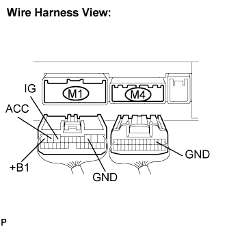 |
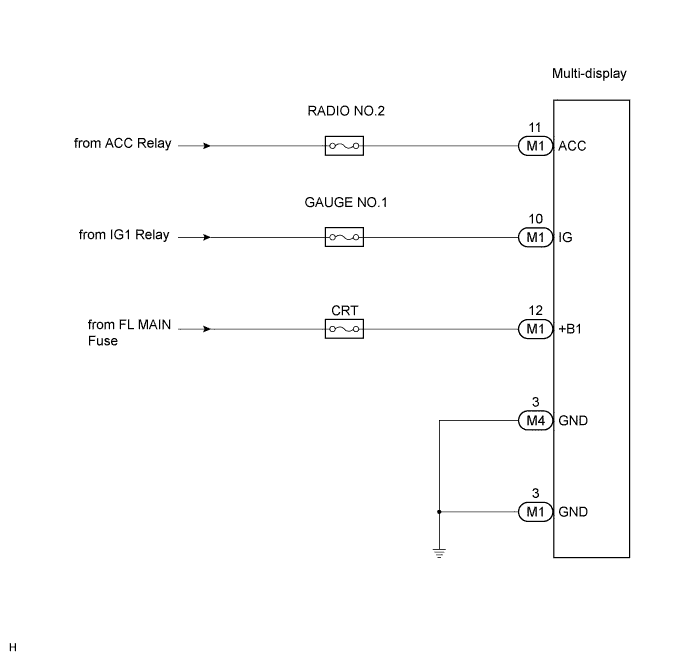
Disconnect the multi-display connectors M4 and M1.
Measure the resistance according to the value(s) in the table below.
| Tester connection | Condition | Specified condition |
| GND (M1-3) - Body ground | Always | Below 1 Ω |
| GND (M4-3) - Body ground | Always | Below 1 Ω |
Measure the voltage according to the value(s) in the table below.
| Tester connection | Condition | Specified condition |
| +B1 - GND | Always | 10 to 14 V |
| ACC - GND | Ignition SW ACC | 10 to 14 V |
| IG - GND | Ignition SW ON | 10 to 14 V |
|
| ||||
| OK | ||
| ||
