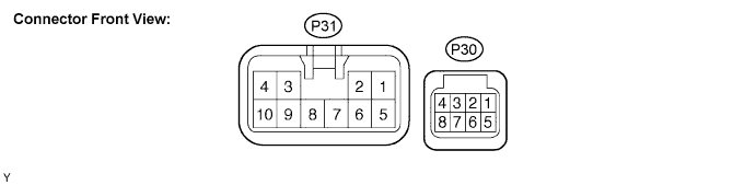
FRONT POWER SEAT CONTROL SYSTEM > TERMINALS OF ECU |
| POSITION CONTROL ECU AND SWITCH ASSEMBLY (POWER SEAT CONTROL SWITCH AND ECU) |
Disconnect the P30 and P31 connectors.
Check the voltage of each terminal of the wire harness side connectors.
| Symbols (Terminal No.) | Wiring Color | Terminal Description | Condition | Specified Condition |
| IG(P30-4) - GND(P31-1) | Y - W-B | Ignition switch signal | Ignition switch off → ignition switch on | Below 1 V → 10 to 14 V |
| SYSB(P30-8) - GND(P31-1) | GR - W-B | Power source | Always | 10 to 14 V |
| +B(P31-5) - GND(P31-1) | LG - W-B | Battery | Always | 10 to 14 V |
Check the resistance of each terminal of the wire harness side connectors.
| Symbols (Terminal No.) | Wiring Color | Terminal Description | Condition | Specified Condition |
| GND(P31-1) - Body ground | W-B - Body ground | Ground | Always | Below 1 Ω |
Reconnect the P30 and P31 connectors.
Check the voltage of each terminal of the connectors.
| Symbols (Terminal No.) | Wiring Color | Terminal Description | Condition | Specified Condition |
| MPX1(P30-1) - GND(P31-1) | W - W-B | Multiplex communication signal circuit | Ignition switch on | Pulse generation |
| SLD+(P31-2) - GND(P31-1) | L - W-B | Sliding motor signal (Forward) | Seat moving forward using sliding switch → Other conditions | 10 to 14 V → Below 1 V |
| SLD-(P31-3) - GND(P31-1) | Y - W-B | Sliding motor signal (Rearward) | Seat moving rearward using sliding switch → Other conditions | 10 to 14 V → Below 1 V |
| FRV-(P31-4) - GND(P31-1) | B - W-B | Front vertical motor signal (Downward) | Seat cushion front portion lowering using front vertical switch → Other conditions | 10 to 14 V → Below 1 V |
| FRV+(P31-6) - GND(P31-1) | G - W-B | Front vertical motor signal (Upward) | Seat cushion front portion rising using front vertical switch → Other conditions | 10 to 14 V → Below 1 V |
| LFT+(P31-7) - GND(P31-1) | W - W-B | Lifter motor signal (Upward) | Seat rising using lifter switch → Other conditions | 10 to 14 V → Below 1 V |
| RCL+(P31-8) - GND(P31-1) | P - W-B | Reclining motor signal (Forward) | Seatback moving forward using reclining switch → Other conditions | 10 to 14 V → Below 1 V |
| LFT-(P31-9) - GND(P31-1) | V - W-B | Lifter motor signal (Downward) | Seat lowering using lifter switch → Other conditions | 10 to 14 V → Below 1 V |
| RCL-(P31-10) - GND(P31-1) | BR - W-B | Reclining motor signal (Rearward) | Seatback moving rearward using reclining switch → Other conditions | 10 to 14 V → Below 1 V |
| POWER WINDOW REGULATOR SWITCH ASSEMBLY (POWER WINDOW MASTER SWITCH) |
Disconnect the P19 connector.

Check the voltage of each terminal of the wire harness side connector.
| Symbols (Terminal No.) | Wiring Color | Terminal Description | Condition | Specified Condition |
| CPUB(P19-9) - GND(P19-2) | L-B - W-B | Power source | Always | 10 to 14 V |
| BDR(P19-10) - GND(P19-2) | G - W-B | Power window motor power source | Always | 10 to 14 V |
| SIG(P19-20) - GND(P19-2) | BR - W-B | Ignition switch signal | Ignition switch off → ignition switch on | Below 1 V → 10 to 14 V |
Check the resistance of each terminal of the wire harness side connector.
| Symbols (Terminal No.) | Wiring Color | Terminal Description | Condition | Specified Condition |
| GND(P19-2) - Body ground | W-B - Body ground | Ground | Always | Below 1 Ω |
Reconnect the P19 connector.
Check the voltage of each terminal of the connector.
| Symbols (Terminal No.) | Wiring Color | Terminal Description | Condition | Specified Condition |
| MM(P19-3) - GND(P19-2) | LG - W-B | SET switch signal | SET switch is not pushed → pushed | 10 to 14 V → Below 1 V |
| M1(P19-13) - GND(P19-2) | G - W-B | SW1 switch signal | SW1 switch is not pushed → pushed | 10 to 14 V → Below 1 V |
| M2(P19-17) - GND(P19-2) | V - W-B | SW2 switch signal | SW2 switch is not pushed → pushed | 10 to 14 V → Below 1 V |
