POWER STEERING GEAR > INSPECTION |
| 1. INSPECT TIE ROD ASSEMBLY LH |
Secure the tie rod assembly LH in a vise.
Install the nut to the stud bolt.
Flip the ball joint back and forth 5 times or more.
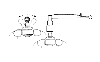 |
Using a torque wrench, turn the nut continuously at a rate of 3 to 5 seconds per turn and take the torque reading on the 5th turn.
| 2. INSPECT TIE ROD ASSEMBLY RH |
| 3. INSPECT TOTAL PRELOAD |
Temporarily install the left and right steering rack ends to prevent steering rack over stroke.
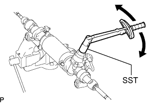 |
Using SST and a torque wrench, inspect total preload.
| 4. INSPECT POWER STEERING LINK ASSEMBLY (TORQUE SENSOR) |
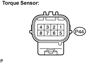 |
Measure the resistance according to the value(s) in the table below.
| Tester connection (Symbols) | Condition | Specified condition |
| P44-1 (INCS) - P44-7 (TQG2) | Always | 90 to 170 Ω P44- |
| P44-2 (INSN) - P44-7 (TQG2) | Always | 300 to 430 Ω |
| P44-4 (TRQV) - P44-8 (TQG1) | Always | 4 to 14 Ω |
| P44-5 (OUCS) - P44-7 (TQG2) | Always | 90 to 170 Ω |
| P44-6 (OUSN) - P44-7 (TQG2) | Always | 300 to 430 Ω |
| 5. INSPECT POWER STEERING LINK ASSEMBLY (POWER STEERING MOTOR) |
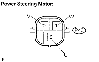 |
Measure the resistance according to the value(s) in the table below.
| Tester connection (Symbols) | Condition | Specified condition |
| P43-3 (U) - P43-2 (V) | Always | Below 1 Ω |
| P43-2 (V) - P43-1 (W) | Always | Below 1 Ω |
| P43-1 (W) - P43-3 (U) | Always | Below 1 Ω |
