POWER STEERING GEAR > REMOVAL |
| 1. PLACE FRONT WHEELS FACING STRAIGHT AHEAD |
| 2. SEPARATE CABLE FROM NEGATIVE BATTERY TERMINAL |
| 3. REMOVE FRONT WHEELS |
| 4. REMOVE ENGINE UNDER COVER NO.2 |
| 5. SEPARATE FRONT STABILIZER LINK ASSEMBLY LH |
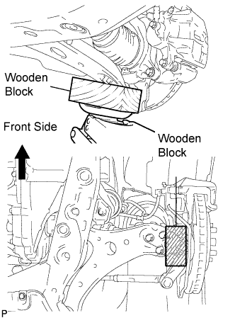 |
Support the front suspension lower arm No.1 with a jack using a wooden block to avoid damage.
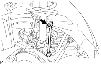 |
Remove the nut and separate the front stabilizer link assembly from the front shock absorber.
| 6. SEPARATE FRONT STABILIZER LINK ASSEMBLY RH |
| 7. SEPARATE STEERING INTERMEDIATE SHAFT SUB-ASSEMBLY |
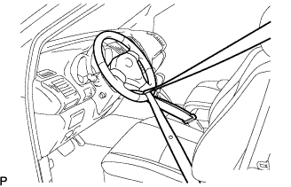 |
Fix the steering wheel with the seat belt in order to prevent rotation.
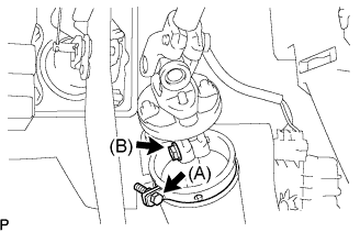 |
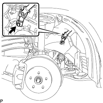
Loosen the bolt (A) and remove the clamp from the steering column hole shield.
Loosen the bolt (B).
 |
Remove the bolt, and then slide the steering intermediate shaft sub-assembly.
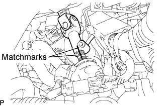 |
Put matchmarks on the steering intermediate shaft sub-assembly and the power steering link assembly.
Separate the steering intermediate shaft sub-assembly from the power steering link assembly.
| 8. SEPARATE TIE ROD ASSEMBLY LH |
Remove the cotter pin and the nut.
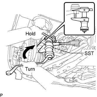 |
Using SST, separate the tie rod assembly LH from the steering knuckle.
| 9. SEPARATE TIE ROD ASSEMBLY RH |
| 10. REMOVE ENGINE ASSEMBLY WITH TRANSAXLE |
| 11. REMOVE POWER STEERING LINK ASSEMBLY |
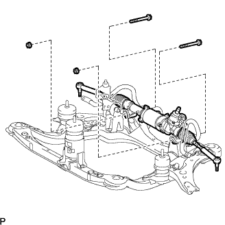 |
Remove the 2 bolts, 2 nuts, and the power steering link assembly from the front frame assembly.
