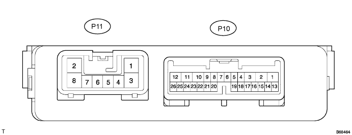
POWER BACK DOOR SYSTEM > TERMINALS OF ECU |
| CHECK POWER BACK DOOR ECU |
Disconnect the P10 and P11 connectors from power back door ECU.
Measure the resistance according to the value(s) in the table below.
| Symbols (Terminal No.) | Wiring Color | Terminal Description | Condition | Specified Condition |
| BDDN (P10-4) - Body ground | W - Body ground | Power back door closer switch signal input | Power back door closer switch OFF → ON | 10 kΩ or higher → Below 1 Ω |
| MSE (P10-5) - MSW (P10-6) | W-B - G | Power back door main switch signal circuit | Power back door main switch OFF → ON | 10 kΩ or higher → Below 1 Ω |
| CTYE (P10-7) - Body ground | P - Body ground | Back door courtesy switch signal input | Back door is closed → opened | 10 kΩ or higher → Below 1 Ω |
| OSL (P10-14) - OSE (P10-15) | G - Y | Power back door touch sensor LH circuit | Back door touch sensor LH not pressed → pressed | Approx. 1 kΩ → Below 100 Ω |
| OSR (P10-16) - OSE (P10-15) | L - Y | Power back door touch sensor RH circuit | Back door touch sensor RH not pressed → pressed | Approx. 1 kΩ → Below 100 Ω |
| CTYO (P10-19) - Body ground | BR - Body ground | Back door courtesy switch signal output | Back door is closed → opened | 10 kΩ or higher → Below 1 Ω |
| GND (P11-8) - Body ground | W-B - Body ground | Ground | Always | Below 1 Ω |
Measure the voltage according to the value(s) in the table below.
| Symbols (Terminal No.) | Wiring Color | Terminal Description | Condition | Specified Condition |
| IG (P10-9) - Body ground | GR - Body ground | Ignition switch input | Ignition switch OFF → ON | Below 1 V → 10 to 14 V |
| ECUB (P10-10) - Body ground | BR - Body ground | ECU power supply | Always | 10 to 14 V |
| MPX1 (P10-22) - Body ground | SB - Body ground | Multiplex communication signal circuit | Ignition switch ON | Signal waveform |
| B (P11-2) - Body ground | Y - Body ground | Motor drive power supply | Always | 10 to 14 V |
Reconnect the P10 and P11 connectors to the back door ECU.
Measure the voltage according to the value(s) in the table below.
| Symbols (Terminal No.) | Wiring Color | Terminal Description | Condition | Specified Condition |
| BZR- (P10-1) - BZR+ (P10-2) | O - B | Power back door warning buzzer signal input | Back door warning buzzer is stopped → sounded | Below 1 V → 10 to 14 V |
| HAF (P10-8) - Body ground | R - Body ground | Back door lock half-latch switch signal input | Back door is opened → back door closer motor is operated → back door is closed | Below 1 V → 10 to 14 V → Below 1 V |
| DC- (P10-11) - DC+ (P10-12) | B - G | Back door closer motor circuit | Back door closer motor is stopped → operated | Below 1 V → 10 to 14 V |
| FUL (P10-18) - Body ground | V - Body ground | Back door lock full-latch switch signal input | Back door is closed → opened | 10 to 14 V → Below 1 V |
| POS (P10-21) - Body ground | LG - Body ground | Back door lock position switch signal input | Back door is opened → back door closer motor is operated → back door is closed | Below 1 V → 10 to 14 V → Below 1 V |
| DS2 (P10-24) - DSG (P10-23) | GR - R | Power back door drive unit pulse sensor 2 signal input circuit | Power back door motor is stopped → operated | Below 1 V → Alternating between 10 to 14 V and below 1 V |
| DS1 (P10-25) - DSG (P10-23) | Y - R | Power back door drive unit pulse sensor 1 signal input circuit | Power back door motor is stopped → operated | Below 1 V → Alternating between 10 to 14 V and below 1 V |
| DSV (P10-26) - DSG (P10-23) | L - R | Power back door drive unit pulse sensor power supply circuit | Always | 10 to 14 V |
| BD+ (P11-1) - BD- (P11-3) | B - W | Power back door drive unit motor circuit | Power back door motor is stopped → operated | Below 1 V → 10 to 14 V |
| CL- (P11-6) - CL+ (P11-7) | G - BR | Power back door drive unit clutch circuit | Power back door motor is stopped → operated | Below 1 V → 10 to 14 V |
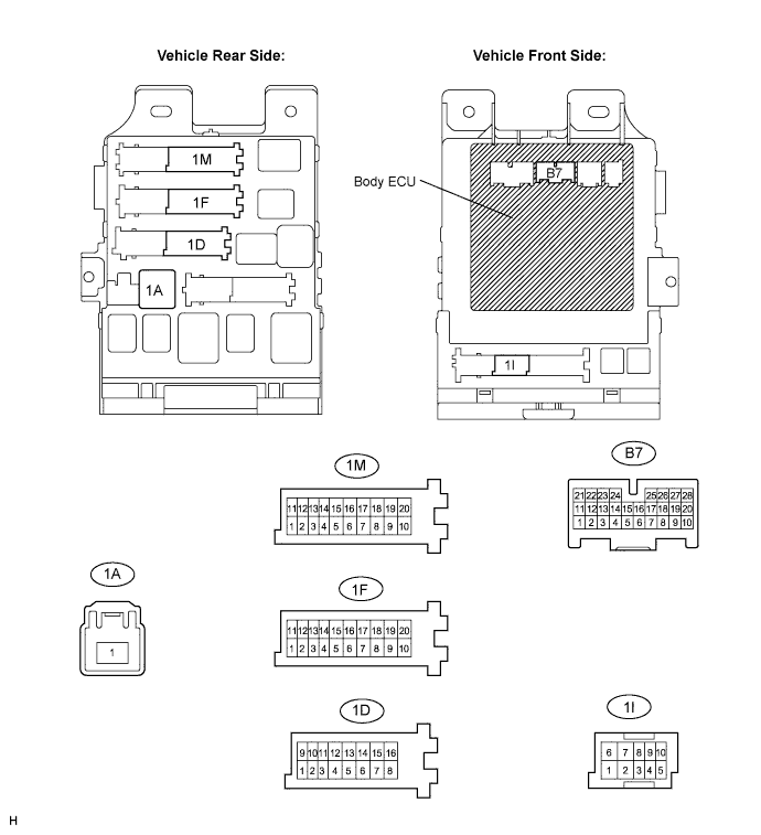
| CHECK INSTRUMENT PANEL JUNCTION BLOCK ASSEMBLY(BODY ECU) |
Disconnect the 1A, 1D, 1F, 1M and B7 connectors from the instrument panel junction block assembly and body ECU.
Measure the resistance according to the value(s) in the table below.
| Symbols (Terminal No.) | Wiring Color | Terminal Description | Condition | Specified Condition |
| GND1 (1F-10) - Body ground | W-B - Body ground | Ground | Always | Below 1 Ω |
| GND2 (1M-9) - Body ground | W-B - Body ground | Ground | Always | Below 1 Ω |
| PBDS (B7-2) - Body ground | V - Body ground | Power back door opener/ closer switch signal input | Power back door opener/closer switch OFF → ON | 10 kΩ or higher → Below 1 Ω |
| BCTY (B7-25) - Body ground | P - Body ground | Back door courtesy light switch signal input | Back door is closed → opened | 10 kΩ or higher → Below 1 Ω |
Measure the voltage according to the value(s) in the table below.
| Symbols (Terminal No.) | Wiring Color | Terminal Description | Condition | Specified Condition |
| BATB (1A-1) - Body ground | B - Body ground | +B (power system, battery system) power supply | Always | 10 to 14 V |
| BECU (1D-10) - Body ground | W - Body ground | +B (BECU) power supply | Always | 10 to 14 V |
| ALTB (1D-16) - Body ground | W - Body ground | +B (power system, generator system) power supply | Always | 10 to 14 V |
Reconnect the 1A, 1D, 1F, 1M and B7 connectors to the instrument panel junction block assembly and body ECU.
Measure the voltage according to the value(s) in the table below.
| Symbols (Terminal No.) | Wiring Color | Terminal Description | Condition | Specified Condition |
| IG (1I-4) - Body ground | O - Body ground | Ignition switch power supply | Ignition switch OFF → ON | 10 to 14 V → Below 1 V |
