BRAKE ACTUATOR > INSTALLATION |
| 1. INSTALL BRAKE ACTUATOR ASSEMBLY |
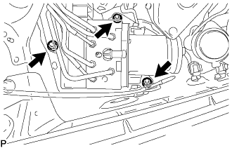 |
Install the brake actuator assembly with bracket to the body with the 3 nuts.
 |
Connect the brake actuator connector.
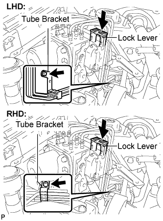
Install the brake tube bracket with the bolt.
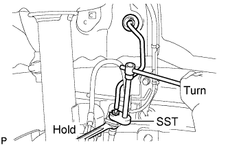 |
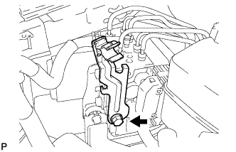
Using SST, connect the front brake No.8 tube to the front flexible hose.
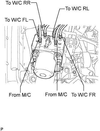 |
Using SST, connect each brake tube to the correct positions on top of the actuator assembly with bracket as shown in the illustration.
 |
Install the brake actuator bracket No.7 with clamp with the bolt.
| 2. INSTALL FRONT WHEEL RH |
| 3. INSTALL BRAKE MASTER CYLINDER RESERVOIR ASSEMBLY |
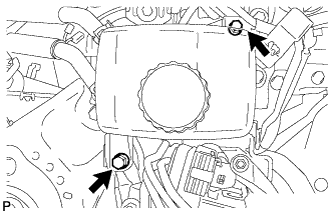 |
Install the brake master cylinder reservoir assembly with the 2 bolts.
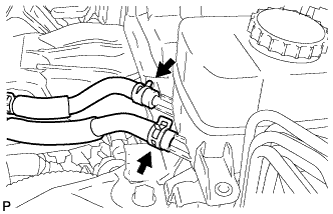 |
Install the 2 reservoir tubes with the 2 clips.
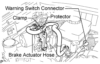 |
Install the brake actuator hose with the 2 clips.
Install the brake actuator hose to the clamp.
Connect the warning switch connector.
| 4. INSTALL COWL PANEL SUB-ASSEMBLY |
Remove the 4 shock absorber nuts.
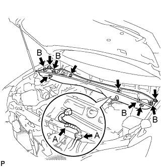 |
Install the 4 bolts, 2 nuts and cowl top panel sub-assembly.
Install the 4 shock absorber nuts (B).
Install the wire harness clamp and grommet (A).
| 5. INSTALL WIND SHIELD WIPER MOTOR ASSEMBLY |
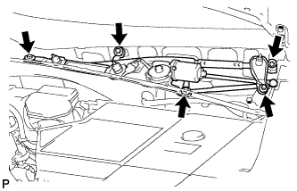 |
Install the windshield wiper motor and link assembly with the 5 bolts.
Connect the connector.
| 6. INSTALL COWL TOP VENTILATOR LOUVER SUB-ASSEMBLY |
Remove the 4 shock absorber nuts.
|
Install the 4 bolts, 2 nuts and cowl top panel sub-assembly.
Install the 4 shock absorber nuts (B).
Install the wire harness clamp and grommet (A).
| 7. INSTALL FRONT WIPER ARM AND BLADE ASSEMBLY RH |
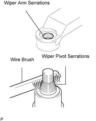 |
Clean the wiper arm serrations.
Clean the wiper pivot serrations with a wire brush (when reinstalling).
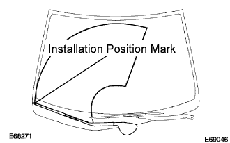 |
Install the front wiper arm and blade assembly RH with the 2 nuts at the position as shown in the illustration.
Operate the front wipers while spraying water or washer fluid on the windshield.
Make sure that the wipers function properly and there is no interference with the vehicle body.
| 8. INSTALL FRONT WIPER ARM AND BLADE ASSEMBLY LH |
|
Operate the front wiper, and stop the front wiper motor at the automatic stop position.
Clean the wiper arm serrations.
Clean the wiper pivot serrations with a wire brush (when reinstalling).
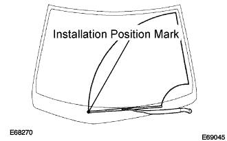 |
Install the front wiper arm and blade assembly LH with the nut at the position as shown in the illustration.
| 9. INSTALL FRONT FENDER TO COWL SIDE SEAL LH |
| 10. INSTALL FRONT FENDER TO COWL SIDE SEAL RH |
| 11. FILL RESERVOIR WITH BRAKE FLUID |
Add brake fluid to the MAX line in the reservoir.
| 12. BLEED BRAKE ACTUATOR HOSE |
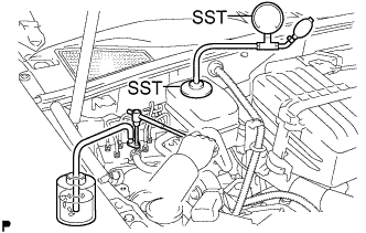 |
Connect SST to the reservoir with the brake reservoir pressure adapter.
Using SST, loosen the bleeder plug of the actuator.
Connect a vinyl tube to the bleeder plug of the actuator.
Use the SST to boost pressure in the reservoir.
Drain approximately 100 cc of fluid.
Tighten the bleeder plug and boost the pressure in the reservoir again (50 to 80 kPa (0.5 to 0.8 kgf/cm2)). Then, loosen the bleeder plug and bleed the brake actuator hose.
When air is completely bled out from the hose between the reservoir and the actuator, tighten the bleeder plug.
| 13. BLEED FRONT BRAKE SYSTEM |
Depress the brake pedal several times and bleed the front brake system from the bleeder plugs on the front brake cylinder RH and LH.
Tighten the bleeder plugs after bleeding.
| 14. INSTALL ABS MOTOR RELAY |
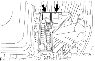 |
Install the 2 ABS motor relays.
| 15. CLEAR DTC |
| 16. BLEED REAR BRAKE SYSTEM |
Connect the intelligent tester to the DLC3 with the ignition switch off.
Check that the parking brake is applied and turn the ignition switch to the ON position.
Turn on the intelligent tester and select "DIAGNOSTIC MENU"→"ABS/VSC"→"ECB UTILITY"→"ECB INVALID".
With the brake pedal depressed, bleed the rear brake system from the bleeder plug on the rear disc brake cylinder LH while the pump motor and solenoid are operating.
Tighten the bleeder plug after bleeding.
Turn the intelligent tester on and select "DIAGNOSTIC MENU"→"ABS/VSC"→"ECB UTILITY"→"ECB INVALID"
With the brake pedal depressed, bleed the rear brake system from the bleeder plug on the rear disc brake cylinder RH while the pump motor and solenoid are operating.
Tighten the bleeder plug after bleeding.
| 17. PERFORM ACCUMULATOR ZERO DOWN |
Connect the intelligent tester to the DLC3 with the ignition switch off
Depressurize the accumulator.
Check that the parking brake is applied and turn the ignition switch to the ON position.
Turn on the intelligent tester and select "DIAGNOSTIC MENU" → "ABS/VSC" → "ECB UTILITY" → "ZERO DOWN" on the intelligent tester.
When the buzzer sounds, turn the ignition switch off.
Circulate the fluid in the accumulator.
Depressurize the accumulator 5 times.
| 18. CHECK BRAKE FLUID LEVEL |
After performing accumulator zero down (accumulator depressurizing), return the fluid in the accumulator back to the reservoir and then adjust the fluid level in the master cylinder reservoir to the MAX level.
| 19. CHECK AND CLEAR DTC |
| 20. PERFORM LINEAR VALVE OFFSET LEARNING |
| 21. CHECK FOR BRAKE FLUID LEAKAGE |
