DTC B2414 Steering Position Sensor Malfunction |
| DTC No. | DTC Detecting Condition | Trouble Area |
| B2414 |
|
|
| 1.CHECK DTC (ELECTRONICALLY CONTROLLED BRAKE SYSTEM) |
Check the electronically controlled brake system (Click here).
|
| ||||
| OK | |
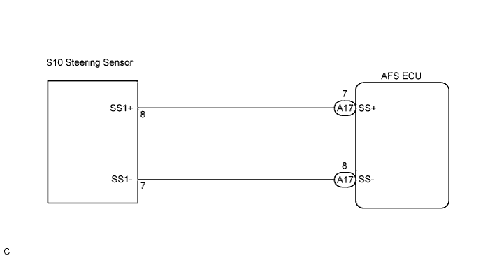
| 2.CHECK HARNESS AND CONNECTOR (STEERING SENSOR - AFS ECU) |
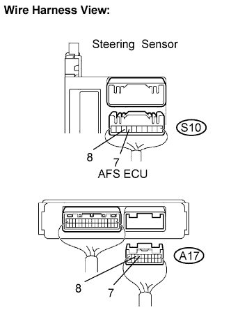 |
Disconnect the steering sensor connector and AFS ECU connector.
Measure the resistance according to the value(s) in the table below.
| Tester connection | Condition | Specified condition |
| SS1- (S10-7) - SS- (A17-8) | Always | Below 1 Ω |
| SS1+ (S10-8) - SS+ (A17-7) | Always | Below 1 Ω |
| SS- (A17-8) - Body ground | Always | 10 kΩ or higher |
| SS+ (A17-7) - Body ground | Always | 10 kΩ or higher |
|
| ||||
| OK | |
| 3.INSPECT AFS ECU |
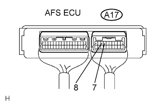 |
Measure the voltage according to the value(s) in the table below.
| Tester connection | Condition | Specified condition |
| SS+ (A17-7) - SS- (A17-8) | Ignition switch ON | 0 to 5 V (Pulse generation) |
| Condition | Proceed to |
| OK (When checking from the DTC) | A |
| OK (When checking from the PROBLEM SYMPTOMS TABLE) | B |
| NG | C |
|
| ||||
|
| ||||
| A | ||
| ||
