DTC B2415 Vehicle Speed Sensor Malfunction |
| DTC No. | DTC Detecting Condition | Trouble Area |
| B2415 |
|
|
| 1.CHECK DTC (ELECTRONICALLY CONTROLLED BRAKE SYSTEM) |
Check the DTC of electronically controlled brake system (Click here).
|
| ||||
| OK | |
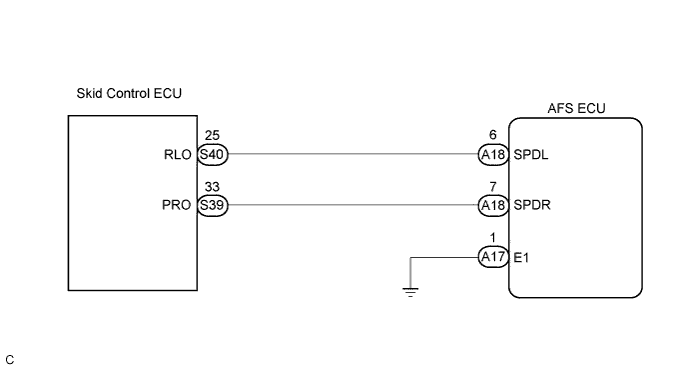
| 2.CHECK HARNESS AND CONNECTOR (SKID CONTROL ECU - AFS ECU) |
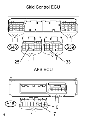 |
Disconnect the skid control ECU connector and AFS ECU connector.
Measure the resistance according to the value(s) in the table below.
| Tester connection | Condition | Specified condition |
| PRO (S39-33) - SPDR (A18-7) | Always | Below 1 Ω |
| RLO (S40-25) - SPDL (A18-6) | Always | Below 1 Ω |
| SPDR (A18-7) - Body ground | Always | 10 kΩ or higher |
| SPDL (A18-6) - Body ground | Always | 10 kΩ or higher |
|
| ||||
| OK | |
| 3.INSPECT AFS ECU |
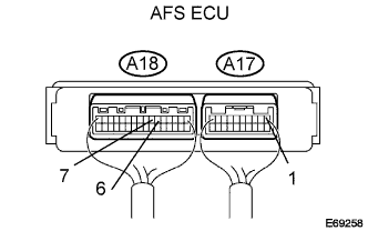 |
Measure the voltage according to the value(s) in the table below.
| Tester connection | Condition | Specified condition |
| SPDL (A18-6) - E1 (A17-1) | Drive at about 30 km/h (19 mph) | 0 to 14 V Pulse generation(*1) |
| SPDR (A18-7) - E1 (A17-1) | Drive at about 30 km/h (19 mph) | 0 to 14 V Pulse generation (*1) |
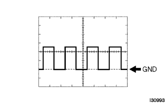 |
*1: Oscilloscope wave
| Condition | Proceed to |
| OK (When checking from the DTC) | A |
| OK (When checking from the PROBLEM SYMPTOMS TABLE) | B |
| NG | C |
|
| ||||
|
| ||||
| A | ||
| ||
