LIGHTING SYSTEM > Illumination Circuit |
| 1.PERFORM ACTIVE TEST BY INTELLIGENT TESTER |
Connect the intelligent tester to the DLC3.
Turn the ignition switch to the ON position and press the intelligent tester main switch ON.
Select the items below in the ACTIVE TEST and then check that the relay operates.
| Item | Test Details | Diagnostic Note |
| Illuminated Entry System | (Test Details) Turn Interior light and Key illumination ON/OFF (Vehicle Condition) Interior light SW is in Door position and all doors are closed | - |
|
| ||||
| OK | ||
| ||
| 2.INSPECT INTERIOR LIGHT |
Inspect ignition key cylinder light (Click here).
Inspect scuff plate illumination (Click here).
Inspect front room light (Click here).
|
| ||||
| OK | |
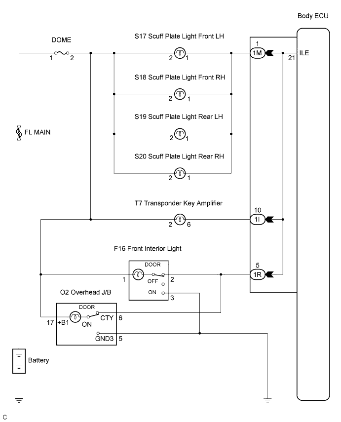
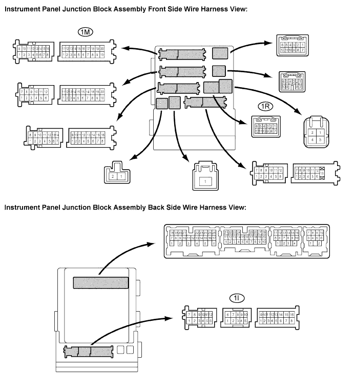
| 3.INSPECT INSTRUMENT PANEL JUNCTION BLOCK ASSEMBLY |
Measure the voltage according to the value(s) in the table below.
| Tester connection | Condition | Specified condition |
| 1I-10 - Body ground | All door is closed → Front or rear door is open | 10 to 14 V → Below 1 V |
| 1M-1 - Body ground | All door is closed → Front or rear door is open | 10 to 14 V → Below 1 V |
| 1R-5 - Body ground | All door is closed → Front or rear door is open | 10 to 14 V → Below 1 V |
|
| ||||
| OK | ||
| ||
