LIGHTING SYSTEM > Headlight Beam Level Control Actuator Circuit |
| 1.INSPECT HEADLIGHT BEAM LEVEL CONTROL MOTOR LH |
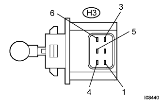 |
Disconnect the connector from headlight beam level control motor LH.
Measure the resistance according to the value(s) in the table below.
| Tester connection | Condition | Specified condition |
| 1 (LH2) - 5 (LHB1) | Always | 26 to 30 Ω |
| 3 (LH4) - 5 (LHB1) | Always | 26 to 30 Ω |
| 4 (LH1) - 5 (LHB1) | Always | 26 to 30 Ω |
| 6 (LH3) - 5 (LHB1) | Always | 26 to 30 Ω |
|
| ||||
| OK | |
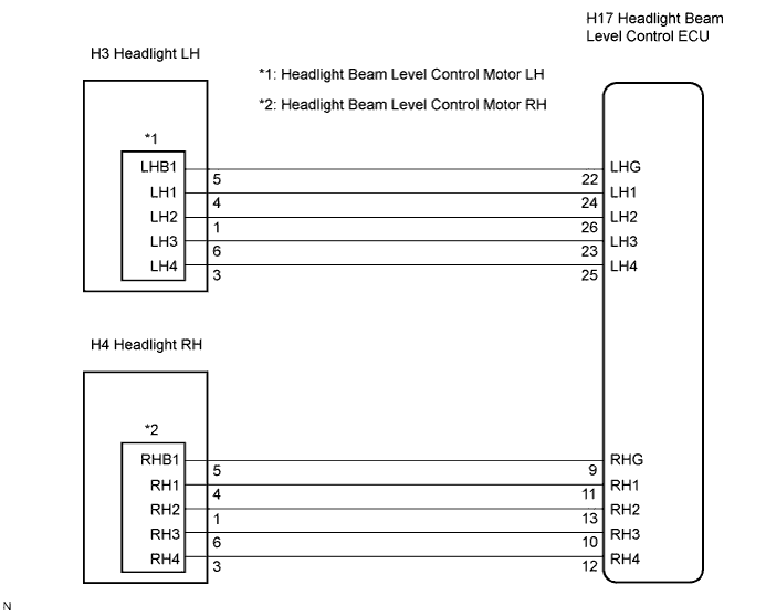
| 2.CHECK HARNESS AND CONNECTOR (LEVEL CONTROL MOTOR LH - LEVEL CONTROL ECU) |
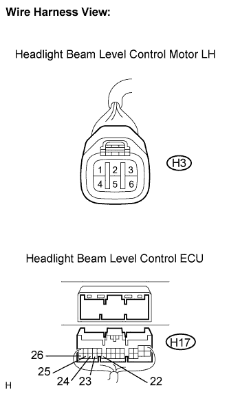 |
Disconnect the H3 connector of headlight beam level control motor LH and the H17 connector of the headlight beam level control ECU.
Measure the resistance according to the value(s) in the table below.
| Tester connection | Condition | Specified condition |
| H3-1 (LH2) - H17-26 (LH2) | Always | Below 1 Ω |
| H3-3 (LH4) - H17-25 (LH4) | Always | Below 1 Ω |
| H3-4 (LH1) - H17-24 (LH1) | Always | Below 1 Ω |
| H3-5 (LHB1) - H17-22 (LHG) | Always | Below 1 Ω |
| H3-6 (LH3) - H17-23 (LH3) | Always | Below 1 Ω |
| H17-26 (LH2) - Body ground | Always | 10 kΩ or higher |
| H17-25 (LH4) - Body ground | Always | 10 kΩ or higher |
| H17-24 (LH1) - Body ground | Always | 10 kΩ or higher |
| H17-22 (LHG) - Body ground | Always | 10 kΩ or higher |
| H17-23 (LH3) - Body ground | Always | 10 kΩ or higher |
|
| ||||
| OK | |
| 3.INSPECT HEADLIGHT BEAM LEVEL CONTROL MOTOR RH |
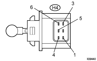 |
Disconnect the connector from headlight leveling motor RH.
Measure the resistance according to the value(s) in the table below.
| Tester connection | Condition | Specified condition |
| 1 (RH2) - 5 (RHB1) | Always | 26 to 30 Ω |
| 3 (RH4) - 5 (RHB1) | Always | 26 to 30 Ω |
| 4 (RH1) - 5 (RHB1) | Always | 26 to 30 Ω |
| 6 (RH3) - 5 (RHB1) | Always | 26 to 30 Ω |
|
| ||||
| OK | |
| 4.CHECK HARNESS AND CONNECTOR (LEVEL CONTROL MOTOR RH - LEVEL CONTROL ECU) |
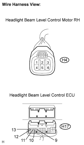 |
Disconnect the H4 connector of headlight beam level control motor RH and the H17 connector of the headlight beam level control ECU.
Measure the resistance according to the value(s) in the table below.
| Tester connection | Condition | Specified condition |
| H4-1 (RH2) - H17-13 (RH2) | Always | Below 1 Ω |
| H4-3 (RH4) - H17-12 (RH4) | Always | Below 1 Ω |
| H4-4 (RH1) - H17-11 (RH1) | Always | Below 1 Ω |
| H4-5 (RHB1) - H17-9 (RHG) | Always | Below 1 Ω |
| H4-6 (RH3) - H17-10 (RH3) | Always | Below 1 Ω |
| H17-13 (RH2) - Body ground | Always | 10 kΩ or higher |
| H17-12 (RH4) - Body ground | Always | 10 kΩ or higher |
| H17-11 (RH1) - Body ground | Always | 10 kΩ or higher |
| H17-9 (RHG) - Body ground | Always | 10 kΩ or higher |
| H17-10 (RH3) - Body ground | Always | 10 kΩ or higher |
|
| ||||
| OK | ||
| ||
