LIGHTING SYSTEM > Door LOCK Position Circuit |
| 1.READ VALUE OF INTELLIGENT TESTER |
Connect the intelligent tester to the DLC3.
Turn the ignition switch to the ON position and press the intelligent tester main switch ON.
Select the items below in the DATA LIST, and read the displays on the intelligent tester.
| Item | Measurement Item/ Display (Range) | Normal Condition | Diagnostic Note |
| P Lock Position | Front passenger's door lock position SW signal/ON or OFF | ON: Front passenger's door lock is in unlock position OFF: Front passenger's door lock is in lock position | - |
| Rear Lock Position SW | Rear door lock position SW signal/ON or OFF | ON: Rear slide door lock is in unlock position OFF: Rear slide door lock is in lock position | - |
| D Lock Position SW | Driver's door lock position SW signal/ON or OFF | ON: Door lock is in unlock position OFF: Door lock is in lock position | - |
|
| ||||
| OK | ||
| ||
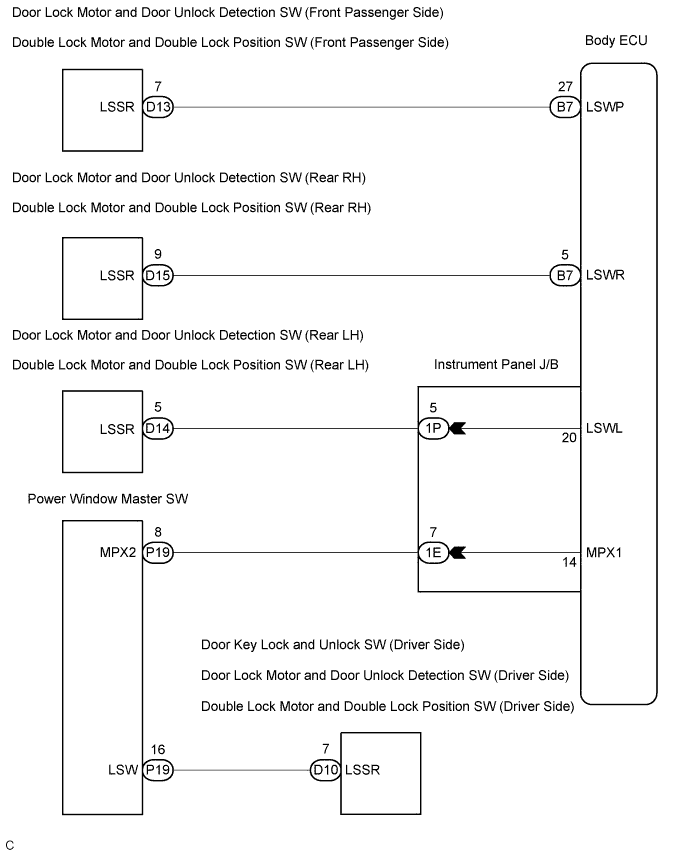
| 2.INSPECT INSTRUMENT PANEL JUNCTION BLOCK ASSEMBLY |
 |
Measure the voltage according to the value(s) in the table below.
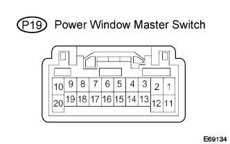
| Tester connection | Condition | Specified condition |
| P19-16 - Body ground | Driver side door is lock → unlock | Below 1 V → 10 to 14 V |
Measure the voltage according to the value(s) in the table below.
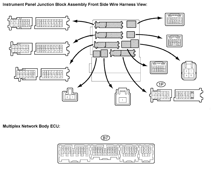
| Tester connection | Condition | Specified condition |
| 1P-5 - Body ground | Rear LH door is lock → unlock | Below 1 V → Pulse generation (*1) |
| B7-5 - Body ground | Rear RH door is lock → unlock | Below 1 V → Pulse generation (*1) |
| B7-27 - Body ground | Front passenger door is lock → unlock | Below 1 V → 10 to 14 V |
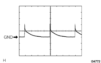 |
*1: Oscilloscope wave
|
| ||||
| OK | ||
| ||
