LIGHTING SYSTEM > Taillight Relay Circuit |
| 1.PERFORM ACTIVE TEST BY INTELLIGENT TESTER |
Connect the intelligent tester to the DLC3.
Turn the ignition switch to the ON position and press the intelligent tester main switch ON.
Select the items below in the ACTIVE TEST and then check that the relay operates.
| Item | Test Details | Diagnostic Note |
| Taillight Relay | Turn Tail light relay ON/OFF | - |
|
| ||||
| OK | ||
| ||
| 2.INSPECT FUSE |
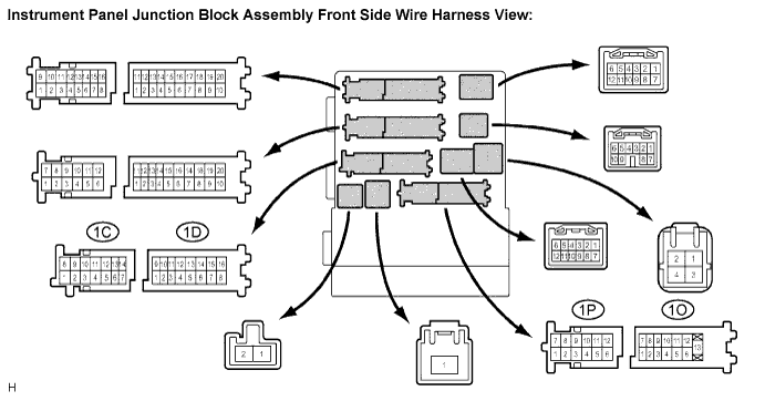
Inspect TAIL fuse in the instrument panel junction block assembly.
|
| ||||
| OK | |
| 3.INSPECT RELAY |
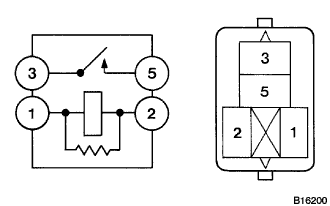 |
Inspect TAIL relay continuity.
Remove the TAIL relay from the instrument panel J/B assembly.
Measure the resistance according to the value(s) in the table below.
| Tester connection | Condition | Specified condition |
| 3 - 5 | Always | 10 kΩ or higher |
| 3 - 5 | Apply B+ between the terminal 1 and 2 | Below 1 Ω |
|
| ||||
| OK | |
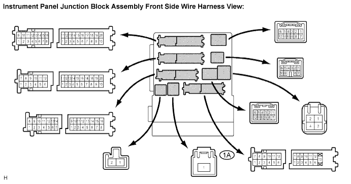
| 4.INSPECT INSTRUMENT PANEL JUNCTION BLOCK ASSEMBLY (POWER SOURCE CIRCUIT) |
Measure the voltage according to the value(s) in the table below.
| Tester connection | Condition | Specified condition |
| 1A-1 - Body ground | Always | 10 to 14 V |
|
| ||||
| OK | |
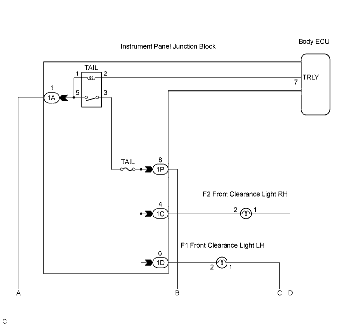
| 5.INSPECT INSTRUMENT PANEL JUNCTION BLOCK ASSEMBLY |
Measure the voltage according to the value(s) in the table below.
| Tester connection | Condition | Specified condition |
| 1C-4 - Body ground | Light control switch OFF → TAIL | Below 1 V → 10 to 14 V |
| 1D-6 - Body ground | Light control switch OFF → TAIL | Below 1 V → 10 to 14 V |
| 1P-8 - Body ground | Light control switch OFF → TAIL | Below 1 V → 10 to 14 V |
|
| ||||
| OK | |
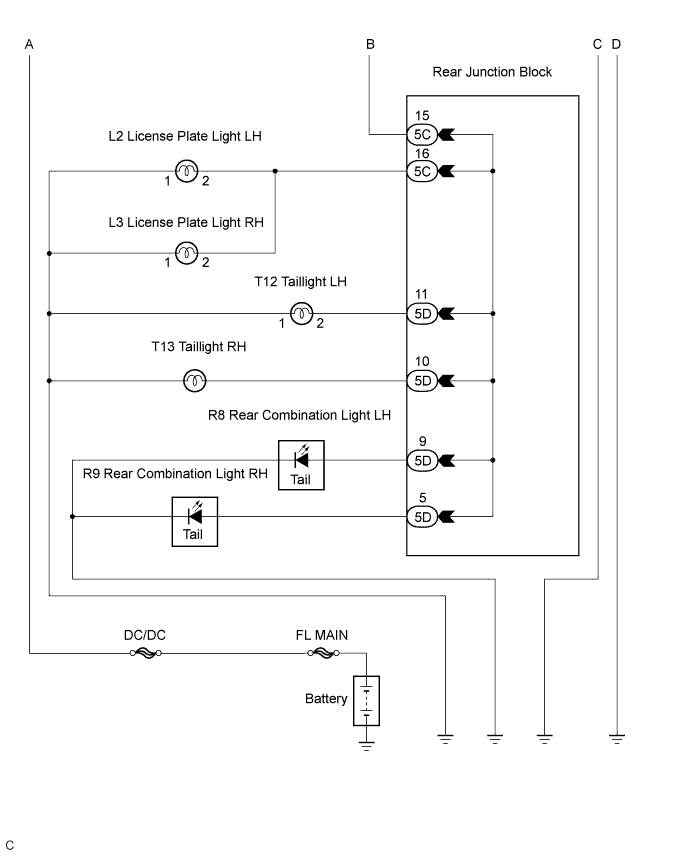
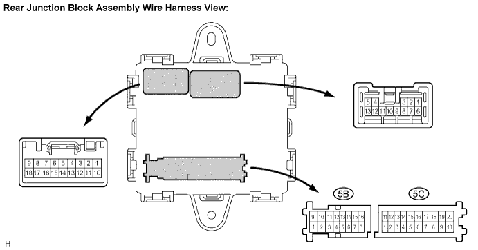
| 6.INSPECT REAR JUNCTION BLOCK |
Measure the voltage according to the value(s) in the table below.
| Tester connection | Condition | Specified condition |
| 5C-15 - Body ground | Light control switch OFF → TAIL | Below 1 V → 10 to 14 V |
|
| ||||
| OK | |
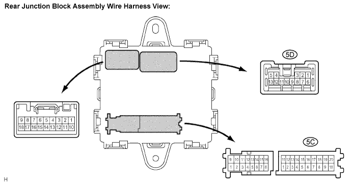
| 7.INSPECT REAR JUNCTION BLOCK |
Measure the voltage according to the value(s) in the table below.
| Tester connection | Condition | Specified condition |
| 5C-16 - Body ground | Headlight dimmer switch OFF → TAIL | Below 1 V → 10 to 14 V |
| 5D-5 - Body ground | Headlight dimmer switch OFF → TAIL | Below 1 V → 10 to 14 V |
| 5D-9 - Body ground | Headlight dimmer switch OFF → TAIL | Below 1 V → 10 to 14 V |
| 5D-10 - Body ground | Headlight dimmer switch OFF → TAIL | Below 1 V → 10 to 14 V |
| 5D-11 - Body ground | Headlight dimmer switch OFF → TAIL | Below 1 V → 10 to 14 V |
|
| ||||
| OK | ||
| ||
