LIGHTING SYSTEM > Headlight Beam Level Control ECU Power Source Circuit |
| 1.INSPECT FUSE |
Inspect the ECU-IG No.2 fuse in the instrument panel junction block assembly.
|
| ||||
| OK | |
| 2.INSPECT RELAY |
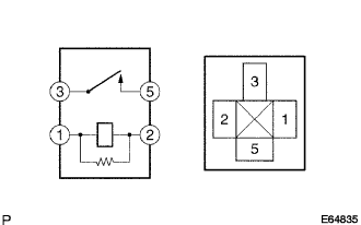 |
Inspect IG1 relay continuity.
Remove the IG1 relay from the instrument panel J/B assembly.
Measure the resistance according to the value(s) in the table below.
| Tester connection | Condition | Specified resistance |
| 3 - 5 | Always | 10 kΩ or higher |
| 3 - 5 | Apply B+ between the terminal 1 and 2 | Below 1 Ω |
|
| ||||
| OK | |
| 3.INSPECT HEADLIGHT BEAM LEVEL CONTROL ECU |
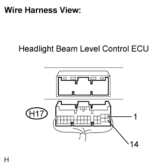 |
Disconnect the H17 connector of headlight beam level control ECU.
Measure the voltage according to the value(s) in the table below.
| Tester connection | Condition | Specified condition |
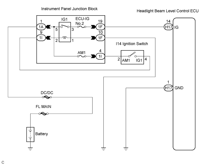
| H17-14 (IG) - H17-1 (GND) | Ignition switch OFF → ON | Below 1 V → 10 to 14 V |
|
| ||||
| OK | ||
| ||
| 4.CHECK HARNESS AND CONNECTOR (HEADLIGHT BEAM LEVEL CONTROL ECU - BODY GROUND) |
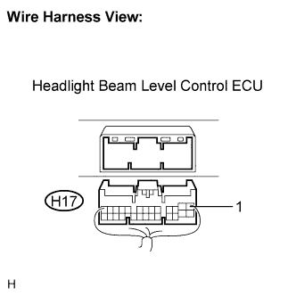 |
Disconnect the H17 connector of headlight beam level control ECU.
Measure the resistance according to the value(s) in the table below.
| Tester connection | Condition | Specified condition |
| H17-1 (GND) - Body ground | Always | Below 1 Ω |
|
| ||||
| OK | |
| 5.INSPECT INSTRUMENT PANEL JUNCTION BLOCK ASSEMBLY (POWER SOURCE CIRCUIT) |
Measure the voltage according to the value(s) in the table below.
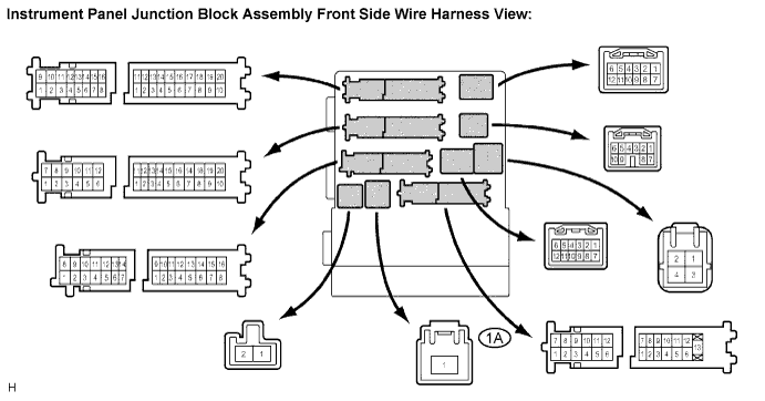
| Tester connection | Condition | Specified condition |
| 1A-1 - Body ground | Always | 10 to 14 V |
|
| ||||
| OK | |
| 6.INSPECT INSTRUMENT PANEL JUNCTION BLOCK ASSEMBLY |
Measure the voltage according to the value(s) in the table below.
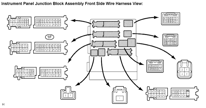
| Tester connection | Condition | Specified condition |
| 1F-19 - Body ground | Ignition switch OFF → ON | Below 1 V → 10 to 14 V |
|
| ||||
| OK | ||
| ||
| 7.INSPECT IGNITION SWITCH |
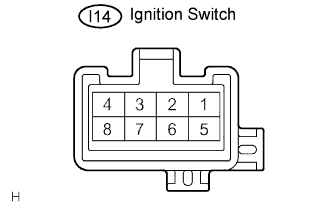 |
Disconnect the ignition switch connector.
Measure the resistance according to the value(s) in the table below.
| Tester connection | Condition | Specified resistance |
| 2 - 4 | Ignition switch OFF | 10 kΩ or higher |
| 2 - 4 | Ignition switch ON | Below 1 Ω |
|
| ||||
| OK | |
| 8.INSPECT INSTRUMENT PANEL JUNCTION BLOCK ASSEMBLY |
Measure the voltage according to the value(s) in the table below.
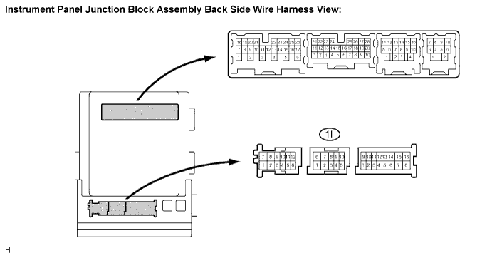
| Tester connection | Condition | Specified condition |
| 1I-4 - Body ground | Always | 10 to 14 V |
|
| ||||
| OK | |
| 9.INSPECT INSTRUMENT PANEL JUNCTION BLOCK ASSEMBLY |
Measure the voltage according to the value(s) in the table below.
| Tester connection | Condition | Specified condition |
| 1I-9 - Body ground | Ignition switch OFF → ON | Below 1 V → 10 to 14 V |
|
| ||||
| OK | |
| 10.CHECK HARNESS AND CONNECTOR (INSTRUMENT PANEL J/B ASSEMBLY - BODY GROUND) |
Disconnect the 1F connector from the instrument panel junction block assembly.
Measure the resistance according to the value(s) in the table below.
| Tester connection | Condition | Specified condition |
| 1F-10 - Body ground | Always | Below 1 Ω |
|
| ||||
| OK | ||
| ||
