DTC C1568 DC-DC Converter Malfunction |
| DTC No. | DTC Detection Condition | Trouble Area |
| C1568 | DC-DC converter malfunction |
|
| 1.CHECK OTHER DTC OUTPUT (HYBRID CONTROL SYSTEM) |
Check for DTCs of the hybrid control system (Click here).
|
| ||||
| OK | |
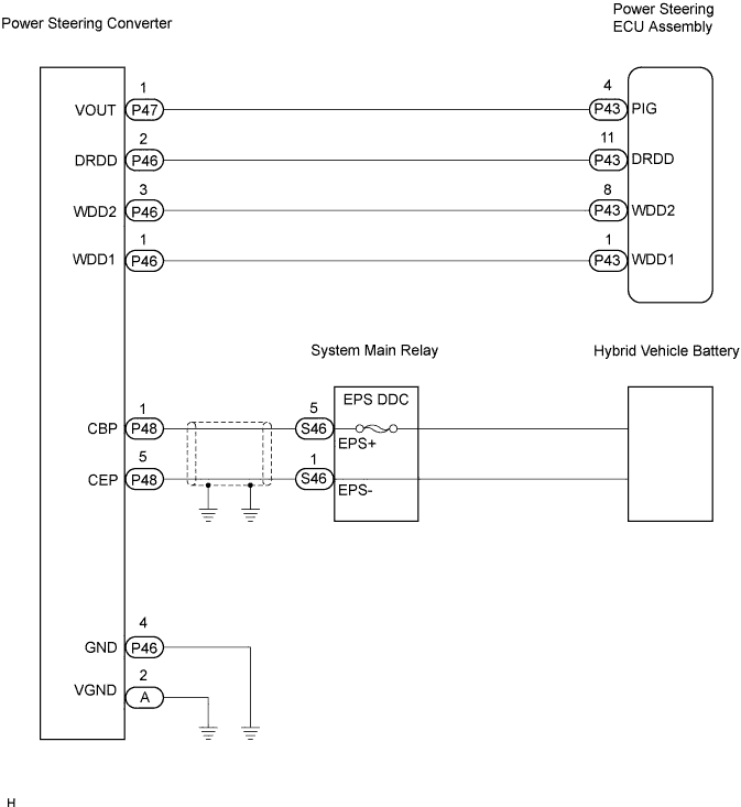
| 2.CHECK HARNESS AND CONNECTOR (BETWEEN POWER STEERING ECU AND POWER STEERING CONVERTER) |
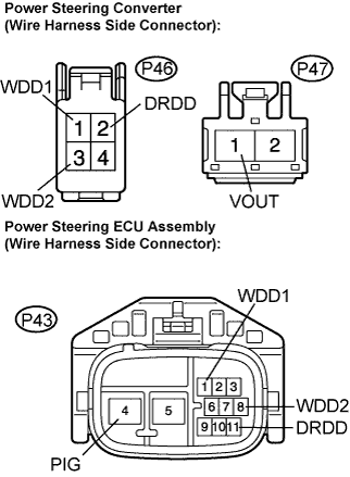 |
Disconnect the P46 and P47 connectors from the power steering converter.
Disconnect the P43 connector from the power steering ECU assembly.
Measure the resistance according to the value(s) in the table below.
| Tester connection (Symbols) | Condition | Specified condition |
| P47-1 (VOUT) - P43-4 (PIG) | Always | Below 1 Ω |
| P46-2 (DRDD) - P43-11 (DRDD) | Always | Below 1 Ω |
| P46-1 (WDD1) - P43-1 (WDD1) | Always | Below 1 Ω |
| P46-3 (WDD2) - P43-8 (WDD2) | Always | Below 1 Ω |
| P47-1 (VOUT) - Body ground | Always | 10 kΩ or higher |
| P46-2 (DRDD) - Body ground | Always | 10 kΩ or higher |
| P46-1 (WDD1) - Body ground | Always | 10 kΩ or higher |
| P46-3 (WDD2) - Body ground | Always | 10 kΩ or higher |
Measure the voltage according to the value(s) in the table below.
| Tester connection (Symbols) | Condition | Specified condition |
| P47-1 (VOUT) - Body ground | IG switch on | Below 1 V |
| P46-2 (DRDD) - Body ground | IG switch on | Below 1 V |
| P46-1 (WDD1) - Body ground | IG switch on | Below 1 V |
| P46-3 (WDD2) - Body ground | IG switch on | Below 1 V |
|
| ||||
| OK | |
| 3.CHECK HARNESS AND CONNECTOR (BETWEEN POWER STEERING ECU AND BODY GROUND) |
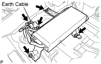 |
Check if the earth cable is securely installed to the vehicle body.
Check if the power steering converter is securely installed to the vehicle body.
Disconnect the P46 and A connectors from the power steering converter.
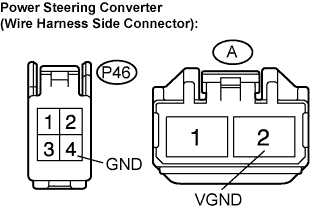 |
Measure the resistance according to the value(s) in the table below.
| Tester connection (Symbols) | Condition | Specified condition |
| P46-4 (GND) - Body ground | Always | Below 1 Ω |
| A-2 (VGND) - Body ground | Always | Below 1 Ω |
|
| ||||
| OK | |
| 4.INSPECT SYSTEM MAIN RELAY (EPS DDC FUSE) |
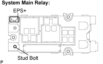 |
Measure the resistance between terminal 5 (EPS+) of the system main relay connector and the stud bolt shown in the illustration to check the internal EPS DDC fuse.
|
| ||||
| OK | |
| 5.CHECK HARNESS AND CONNECTOR (POWER STEERING CONVERTER TO SYSTEM MAIN RELAY) |
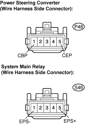 |
Disconnect the P48 connector from the power steering converter.
Disconnect the S46 connector from the system main relay.
Measure the resistance according to the value(s) in the table below.
| Tester connection (Symbols) | Condition | Specified condition |
| P48-1 (CBP) - S46-5 (EPS+) | Always | Below 1 Ω |
| P48-5 (CEP) - S46-1 (EPS-) | Always | Below 1 Ω |
|
| ||||
| OK | |
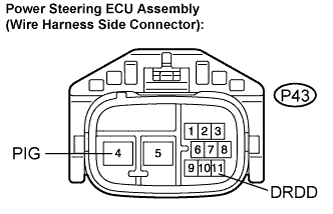
| 6.CHECK POWER STEERING CONVERTER |
 |
Turn the ignition switch off.
Disconnect the P43 connector from the power steering ECU assembly.
Connect the positive battery terminal to terminal P43-11 (DRDD) of the wire harness side connector of the power steering ECU assembly.
Measure the voltage according to the value in the table below.
| Tester connection (Symbols) | Condition | Specified condition |
| P43-4 (PIG) - Body ground | READY ON | 42 to 45 V |
|
| ||||
| OK | ||
| ||
