POWER MIRROR CONTROL SYSTEM (w/ Memory) > Mirror Switch Circuit |
| 1.READ VALUE ON INTELLIGENT TESTER |
Check the DATA LIST for proper function of the outer mirror switches.
| Item | Test Details | Diagnostic Note |
| Mirror Selection SW (R) | Mirror selection switch signal for RH mirror/ON or OFF | ON: Switch is in Right position OFF: Switch is in neutral or Left position |
| Mirror Selection SW (L) | Mirror selection switch signal for LH mirror/ON or OFF | ON: Switch is in Left position OFF: Switch is in neutral or Right position |
| Mirror Position SW (R) | Mirror position switch signal (Right)/ON or OFF | ON: Switch R is ON OFF: Any switch except R is ON or all switches are OFF |
| Mirror Position SW (L) | Mirror position switch signal (Left)/ON or OFF | ON: Switch L is ON OFF: Any switch except L is ON or all switches are OFF |
| Mirror Position SW (Up) | Mirror position switch signal (Up)/ON or OFF | ON: Switch UP is ON OFF: Any switch except UP is ON or all switches are OFF |
| Mirror Position SW (Dwn) | Mirror position switch signal (Down)/ON or OFF | ON: Switch DOWN is ON OFF: Any switch except DOWN is ON or all switches are OFF |
|
| ||||
| OK | ||
| ||
| 2.INSPECT OUTER MIRROR SWITCH |
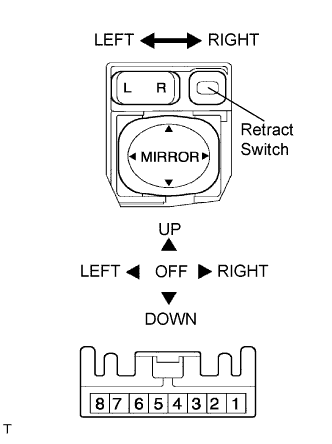 |
Remove the outer mirror switch.
Measure the resistance according to the value(s) in the table below when the switch is operated.
| Tester Connection | Switch Position | Specified Condition |
| 2 - 3 | OFF | 10 kΩ or higher |
| UP | 225 to 275 Ω | |
| DOWN | 437 to 503 Ω | |
| LEFT | 744 to 856 Ω | |
| RIGHT | 437 to 503 Ω | |
| 1 - 2 | L | 90 to 110 Ω |
| R | 10 Ω or less |
|
| ||||
| OK | |
| 3.CHECK WIRE HARNESS (OUTER MIRROR SWITCH - BODY ECU) |
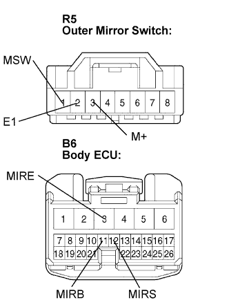 |
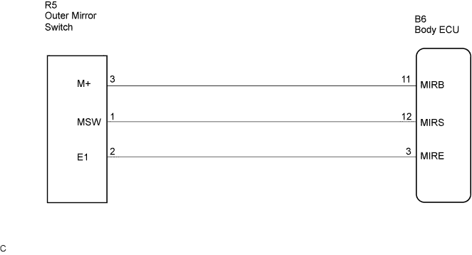
Disconnect the R5 and B6 connectors.
Measure the resistance according to the value(s) in the table below.
| Tester Connection | Condition | Specified Condition |
| R5-3 (M+) - B6-11 (MIRB) | Always | Below 1 Ω |
| R5-1 (MSW) - B6-12 (MIRS) | Always | Below 1 Ω |
| R5-2 (E1) - B6-3 (MIRE) | Always | Below 1 Ω |
| R5-3 (M+) - Body ground | Always | 10 kΩ or higher |
| R5-1 (MSW) - Body ground | Always | 10 kΩ or higher |
| R5-2 (E1) - Body ground | Always | 10 kΩ or higher |
|
| ||||
| OK | ||
| ||
