POWER MIRROR CONTROL SYSTEM (w/ Memory) > Power Source Circuit |
| 1.INSPECT OUTER MIRROR CONTROL ECU (POWER SOURCE) |
 |
Disconnect the R17 (R18) connector.
Measure the voltage and resistance according to the value(s) in the table below.
| Tester Connection | Condition | Specified Condition |
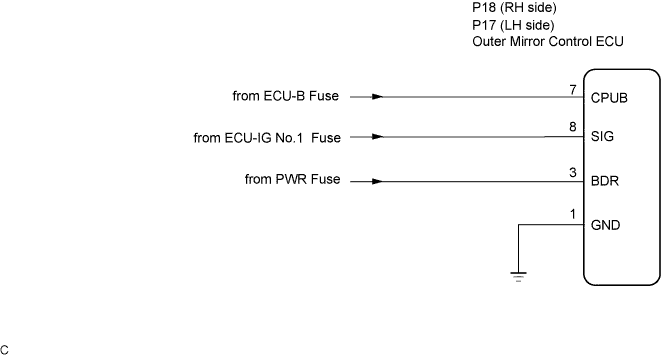
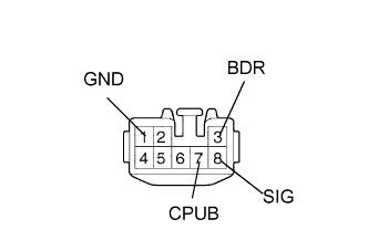
| R17-3 (BDR) - Body ground | Always | 10 to 14 V |
| R17-7 (CPUB) - Body ground | Always | 10 to 14 V |
| R17-8 (SIG) - Body ground | Ignition switch ON | 10 to 14 V |
| Tester Connection | Condition | Specified Condition |
| R17-1 (GND) - Body ground | Always | Below 1 Ω |
| Tester Connection | Condition | Specified Condition |
| R18-3 (BDR) - Body ground | Always | 10 to 14 V |
| R18-7 (CPUB) - Body ground | Always | 10 to 14 V |
| R18-8 (SIG) - Body ground | Ignition switch ON | 10 to 14 V |
| Tester Connection | Condition | Specified Condition |
| R18-1 (GND) - Body ground | Always | Below 1 Ω |
|
| ||||
| OK | ||
| ||
