POWER MIRROR CONTROL SYSTEM (w/ Memory) > Driving Position Memory Switch Circuit (w/ Memory) |
| 1.CHECK SEAT MEMORY SWITCH |
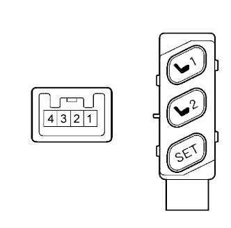 |
Remove the seat memory switch.
Measure the resistance according to the value(s) in the table below when the switch is operated.
| Tester Connection | Switch Condition | Specified Condition |
| 3 - 4 | "SET" switch ON | Below 1 Ω |
| 1 - 4 | "1" switch ON | Below 1 Ω |
| 2 - 4 | "2" switch ON | Below 1 Ω |
|
| ||||
| OK | |
| 2.CHECK WIRE HARNESS (SEAT MEMORY SWITCH - MULTIPLEX NETWORK MASTER SWITCH) |
 |
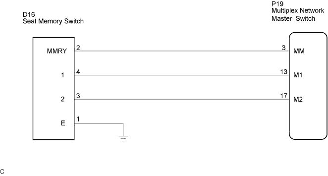
Disconnect the D16 and P19 switch connectors.
Measure the resistance according to the value(s) in the table below.
| Tester Connection | Condition | Specified Condition |
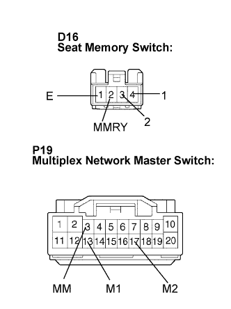
| D16-2 (MMRY) - P19-3 (MM) | Always | Below 1 Ω |
| D16-4 (1) - P19-13 (M1) | Always | Below 1 Ω |
| D16-3 (2) - P19-17 (M2) | Always | Below 1 Ω |
| D16-1 (E) - Body ground | Always | Below 1 Ω |
|
| ||||
| OK | ||
| ||
