OUTER MIRROR SWITCH > INSPECTION |
| 1. INSPECT OUTER MIRROR SWITCH (W/ MEMORY SEAT) |
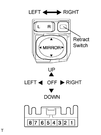 |
Inspect the outer mirror switch operation.
Select "L" on the left/right adjustment switch.
Measure the resistance according to the value(s) in the table below when the switch is operated.
| Tester Connection | Switch Position | Specified Condition |
| 2 - 3 | OFF | 10 kΩ or higher |
| UP | 225 to 275 Ω | |
| DOWN | 437 to 503 Ω | |
| LEFT | 744 to 856 Ω | |
| RIGHT | 437 to 503 Ω | |
| 1 - 2 | L | 90 to 110 Ω |
| R | 10 Ω or less |
Inspect the retract switch operation.
Measure the resistance according to the value(s) in the table below when the switch is operated.
| Tester Connection | Switch Position | Specified Condition |
| 4 - 7 | OFF | 10 kΩ or higher |
| ON | Below 1 Ω |
| 2. INSPECT OUTER MIRROR SWITCH (W/O MEMORY SEAT) |
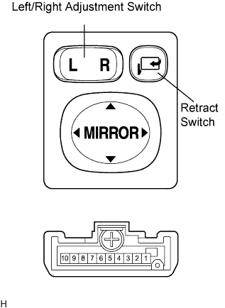 |
Inspect the outer mirror switch.
Select "L" on the left/right adjustment switch.
Measure the resistance according to the value(s) in the table below when the switch is operated.
| Tester Connection | Switch Position | Specified Condition |
| 4 - 8 | UP | Below 1 Ω |
| 6 - 7 | ||
| 4 - 7 | DOWN | |
| 6 - 8 | ||
| 5 - 8 | LEFT | |
| 6 - 7 | ||
| 5 - 7 | RIGHT | |
| 6 - 8 |
| Tester Connection | Switch Position | Specified Condition |
| 3 - 8 | UP | Below 1 Ω |
| 6 - 7 | ||
| 3 - 7 | DOWN | |
| 6 - 8 | ||
| 2 - 8 | LEFT | |
| 6 - 7 | ||
| 2 - 7 | RIGHT | |
| 6 - 8 |
Inspect the retract switch operation.
Measure the resistance according to the value(s) in the table below when the switch is operated.
| Tester Connection | Switch Position | Specified Condition |
| 7 - 9 8 - 10 | OFF | Below 1 Ω |
| 7 - 10 8 - 9 | ON |
