ENGINE IMMOBILISER SYSTEM > TERMINALS OF ECU |
| CHECK TRANSPONDER KEY AMPLIFIER |
Disconnect the T7 amplifier connector and measure the resistance between the terminal of the wire harness side connector and body ground.

| Symbols (Terminal No.) | Wiring Color | Terminal Description | Condition | Specified Condition |
| GND (T7-7) - Body ground | W - Body ground | Ground | Always | Below 1 Ω |
Reconnect the T8 amplifier connector and measure the resistance and voltage of each terminal of the connector.
| Symbols (Terminal No.) | Wiring Color | Terminal Description | Condition | Specified Condition |
| VC5 (T7-1) - GND (T7-7) | P - W | Power source | No key is in ignition key cylinder | Below 1 V |
| Key is in ignition key cylinder | 4.6 to 5.4 V | |||
| CODE (T7-4) - GND (T7-7) | LG - W | Demodulated signal of key code date | No key is in ignition key cylinder | Below 1 V |
| Key is in ignition key cylinder | Waveform 1 | |||
| TEXT (T7-5) - GND (T7-7) | BR - W | Key code output signal | No key is in ignition key cylinder | Below 1 V |
| Key is in ignition key cylinder | Waveform 2 | |||
| GND (T7-7) - Body ground | W - Body ground | Ground | Always | Below 1 Ω |
Inspect using an oscilloscope.
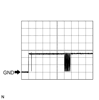 |
Waveform 1 (Reference):
| Terminal | CODE - GND |
| Tool Setting | 2 V/DIV., 20 ms/DIV. |
| Condition | Key is in ignition key cylinder |
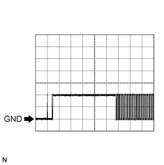 |
Waveform 2 (Reference):
| Terminal | TXCT - GND |
| Tool Setting | 2 V/DIV., 10 ms/DIV. |
| Condition | Key is in ignition key cylinder |
| CHECK TRANSPONDER KEY ECU ASSEMBLY |
Disconnect the T8 ECU connector and measure the resistance and voltage between each terminal of the wire harness side connector.

| Symbols (Terminal No.) | Wiring Color | Terminal Description | Condition | Specified Condition |
| CPUB (T8-1) - GND (T8-14) | V - W-B | Battery | Always | 10 to 14 V |
| IG2 (T8-2) - GND (T8-14) | V - W | Ignition switch | Ignition switch off | Below 1 V |
| Ignition switch on | 10 to 14 V | |||
| KSW (T8-3) - GND (T8-14) | B - W | Unlock warning switch | No key is in ignition key cylinder | 10 kΩ or higher |
| Key is in ignition key cylinder | Below 1 Ω | |||
| MPX1 (T8-4) - Body ground | O - Body ground | MPX line | Always | 10 kΩ or higher |
| MPX2 (T8-5) - Body ground | R (LHD) - Body ground | MPX line | Always | 10 kΩ or higher |
| MPX2 (T8-5) - Body ground | Y (RHD) - Body ground | MPX line | Always | 10 kΩ or higher |
Reconnect the T8 ECU connector and measure the voltage of each terminal of the connector.
| Symbols (Terminal No.) | Wiring Color | Terminal Description | Condition | Specified Condition |
| AGND (T8-13) - Body ground | W - Body ground | Ground | Always | Below 1 Ω |
| KSW (T8-3) - GND (T8-14) | B - W | Unlock warning switch | No key is in ignition key cylinder | 10 to 14 V |
| Key is in ignition key cylinder | Below 1 V | |||
| VC5 (T8-9) - AGND (T8-13) | P - W | Power source | Ignition switch off | Below 1 V |
| Ignition switch on | 4.6 to 5.4 V | |||
| TXCT (T8-12) - AGND (T8-13) | BR - W | Transponder key amplifier communication signal | No key is in ignition key cylinder | Below 1 V |
| Key is in ignition key cylinder | Waveform 1 | |||
| CODE (T8-10) - AGND (T8-13) | LG - W | Transponder key amplifier ground | No key is in ignition key cylinder | Below 1 V |
| Key is in ignition key cylinder | Waveform 2 | |||
| EFIO (T8-6) - GND (T8-14) | GR - W | Hybrid vehicle control ECU output signal | Ignition switch off | Below 1 V |
| Ignition switch on | Waveform 3 | |||
| EFII (T8-7) - GND (T8-14) | L - W | Hybrid vehicle control ECU input signal | Ignition switch off | Below 1 V |
| Ignition switch on | Waveform 4 |
Inspect using an oscilloscope.
|
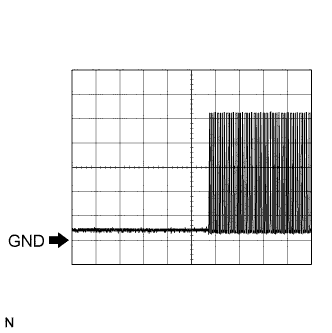
Waveform 1 (Reference):
| Terminal | TXCT - AGND |
| Tool Setting | 2 V/DIV., 10 ms/DIV. |
| Condition | Key is in ignition key cylinder |
|
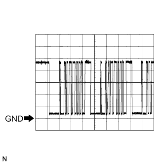
Waveform 2 (Reference):
| Terminal | CODE - AGND |
| Tool Setting | 2 V/DIV., 20 ms/DIV. |
| Condition | Key is in ignition key cylinder |
 |
Waveform 3 (Reference):
| Terminal | EFIO - GND |
| Tool Setting | 2 V/DIV., 1 s/DIV. |
| Condition | Ignition switch on |
 |
Waveform 4 (Reference):
| Terminal | EFII - GND |
| Tool Setting | 2 V/DIV., 200 ms/DIV. |
| Condition | Ignition switch on |
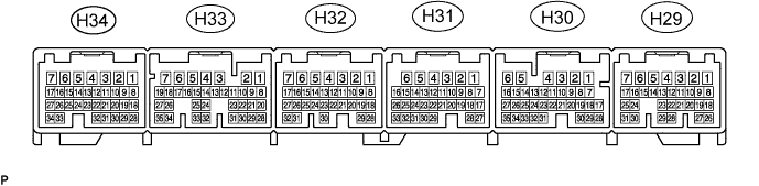
| CHECK HYBRID VEHICLE CONTROL ECU |
Disconnect the H32 hybrid vehicle control ECU connector and measure the resistance between the terminal of the wire harness side connector and body ground.
| Symbols (Terminal No.) | Wiring Color | Terminal Description | Condition | Specified Condition |
| E1 (H32-5) - Body ground | BR - Body ground | Ground | Always | Below 1 Ω |
Reconnect the H32 hybrid vehicle control ECU. Measure the voltage between each terminal of the connector according to the value(s) in the table below.
| Symbols (Terminal No.) | Wiring Color | Terminal Description | Condition | Specified Condition |
| IMI (H29-22) - E1 (H32-5) | GR - BR | Transponder key ECU input signal | Ignition switch off | Below 1 V |
| Ignition switch on | Waveform 1 | |||
| IMO (H29-28) - E1 (H32-5) | L- BR | Transponder key ECU output signal | Ignition switch off | Below 1 V |
| Ignition switch on | Waveform 2 |
Inspect using an oscilloscope.
|
Waveform 1 (Reference):
| Terminal | IMI - E1 |
| Tool Setting | 2 V/DIV., 1 s/DIV. |
| Condition | Ignition switch on |
|
Waveform 2 (Reference):
| Terminal | IMO - E1 |
| Tool Setting | 2 V/DIV., 200 ms/DIV. |
| Condition | Ignition switch on |
