DTC B2797 Communication Malfunction No. 1 |
| DTC No. | DTC Detection Condition | Trouble Area |
| B2797 | Keys are positioned too close to each other, or noise occurs in communication line. |
|
| 1.CHECK KEY |
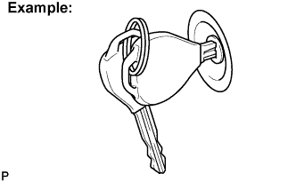 |
Check whether the ignition key being used is near other ignition keys, as shown in the illustration. Also, check whether the key ring is in contact with the key grip.
| Result | Proceed to |
| Key is near other keys and/or key ring is in contact with key grip. | A |
| Key is not near other keys and/or key ring is not in contact with key grip. | B |
|
| ||||
| A | |
| 2.CHECK FOR DTC |
Delete the DTC (Click here).
Insert the key into the ignition key cylinder.
Check that no code is output.
|
| ||||
| NG | |
| 3.CHECK TRANSPONDER KEY AMPLIFIER |
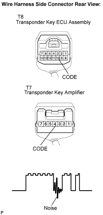 |
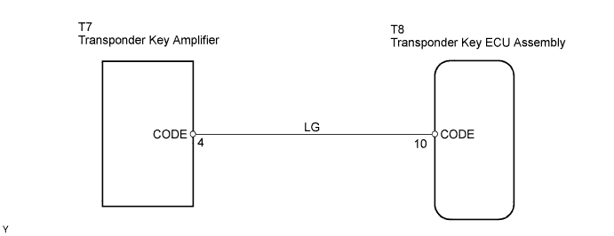
Using an oscilloscope or the intelligent tester, check the waveform between the terminals of the T7 amplifier and T8 ECU connector.
Check that no noise is included in the waveform (an example of noise is shown on the left).
Check that no noise is included in the waveform (an example of noise is shown on the left).
| Tester Connection | Specified Condition |
| T7-4 (CODE) - T8-10 (CODE) | No noise is present |
| Tool Setting | 2 V/DIV., 20 ms/DIV. |
| Condition | Key inserted into ignition key cylinder. |
|
| ||||
| OK | |
| 4.CHECK HARNESS AND CONNECTOR (TRANSPONDER KEY ECU - TRANSPONDER KEY AMPLIFIER) |
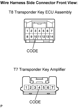 |
Disconnect the T8 ECU and T7 amplifier connectors.
Measure the resistance according to the value(s) in the table below.
| Tester Connection | Specified Condition |
| T8-10 (CODE) - T7-4 (CODE) | Below 1 Ω |
|
| ||||
| OK | |
| 5.CHECK OPERATION OF TRANSPONDER KEY AMPLIFIER |
After replacing the transponder key amplifier with a normally functioning transponder key amplifier, check that the hybrid control system starts.
|
| ||||
| OK | ||
| ||
