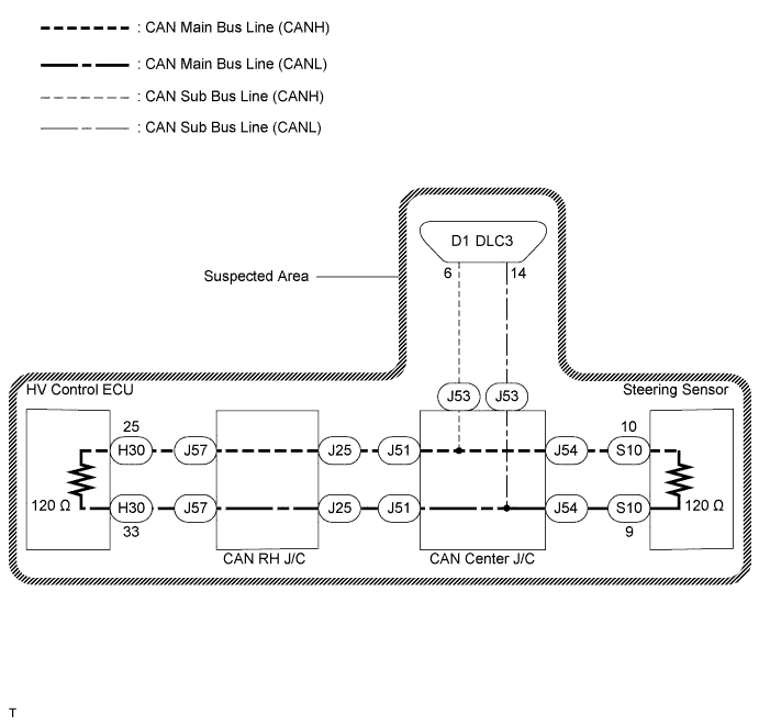
CAN COMMUNICATION SYSTEM (for LHD) > Open in CAN Main Bus Line |
| Symptom | Suspected Area |
| Resistance between terminals 6 (CANH) and 14 (CANL) of the DLC3 is 69 Ω or higher. |
|
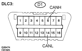
| 1.CHECK DLC3 |
Turn the ignition switch off.
 |
Measure the resistance according to the value(s) in the table below.
| Tester Connection | Condition | Specified Value | Proceed to |
| D1-6 (CANH) - D1-14 (CANL) | Disconnect the negative auxiliary battery cable | 108 to 132 Ω | A |
| D1-6 (CANH) - D1-14 (CANL) | Disconnect the negative auxiliary battery cable | 132 Ω or higher | B |
|
| ||||
| A | |
| 2.CHECK CAN MAIN BUS LINE FOR DISCONNECTION (BUS CHECK) |
Perform "Communication BUS CHECK" using the intelligent tester (Click here).
| Specified Condition | Proceed to |
| "STEERING SENSOR" only is not displayed | A |
| "HV CONTROL" only is not displayed | B |
| Others | C |
|
| ||||
|
| ||||
| A | |
| 3.CHECK CAN MAIN BUS LINE FOR DISCONNECTION (STEERING SENSOR - CAN CENTER J/C) |
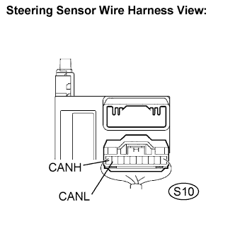 |
Disconnect the steering sensor connector (S10).
Measure the resistance according to the value(s) in the table below.
| Tester Connection | Condition | Specified Value |
| S10-10 (CANH) - S10-9 (CANL) | Disconnect the negative auxiliary battery cable | 108 to 132 Ω |
|
| ||||
| OK | ||
| ||
| 4.CHECK CAN MAIN BUS LINE FOR DISCONNECTION (HV CONTROL ECU - CAN RH J/C) |
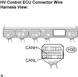 |
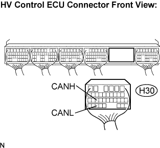
Disconnect the HV control ECU connector (H30).
Measure the resistance according to the value(s) in the table below.
| Tester Connection | Condition | Specified Value |
| H30-25 (CANH) - H30-33 (CANL) | Disconnect the negative auxiliary battery cable | 108 to 132 Ω |
|
| ||||
| OK | ||
| ||
| 5.CHECK CAN MAIN BUS LINE FOR DISCONNECTION |
|
Disconnect the steering sensor connector (S10).
Measure the resistance according to the value(s) in the table below.
| Tester Connection | Condition | Specified Value |
| S10-10 (CANH) - S10-9 (CANL) | Disconnect the negative auxiliary battery cable | 108 to 132 Ω |
|
| ||||
| NG | |
| 6.CONNECT CONNECTOR |
Reconnect the steering sensor connector (S10).
| NEXT | |
| 7.CHECK CAN MAIN BUS LINE FOR DISCONNECTION |
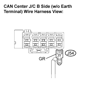 |
Disconnect the steering sensor main bus line connector (J54) from the CAN center J/C B side (w/o earth terminal).
Measure the resistance according to the value(s) in the table below.
| Tester Connection | Condition | Specified Value |
| J54-1 (CANH) - J54-2 (CANL) | Disconnect the negative auxiliary battery cable | 108 to 132 Ω |
|
| ||||
| OK | |
| 8.CONNECT CONNECTOR |
Reconnect the steering sensor main bus line connector (J54) to the CAN center J/C B side (w/o earth terminal).
| NEXT | |
| 9.CHECK CAN MAIN BUS LINE FOR DISCONNECTION |
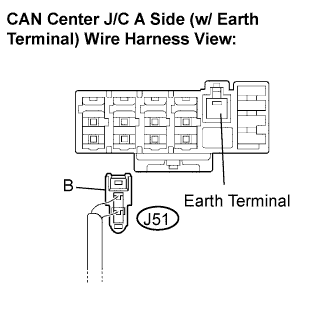 |
Disconnect the CAN main bus line connector (J51) from the CAN center J/C A side (w/ earth terminal).
Measure the resistance according to the value(s) in the table below.
| Tester Connection | Condition | Specified Value |
| J51-1 (CANH) - J51-2 (CANL) | Disconnect the negative auxiliary battery cable | 108 to 132 Ω |
|
| ||||
| NG | |
| 10.CONNECT CONNECTOR |
Reconnect the CAN main bus line connector (J51) to the CAN center J/C A side (w/ earth terminal).
| NEXT | |
| 11.CHECK CAN MAIN BUS LINE FOR DISCONNECTION |
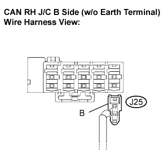 |
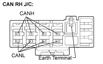
Disconnect the CAN main bus line connector (J25) from the CAN RH J/C B side (w/o earth terminal).
Measure the resistance according to the value(s) in the table below.
| Tester Connection | Condition | Specified Value |
| J25-1 (CANH) - J25-2 (CANL) | Disconnect the negative auxiliary battery cable | 108 to 132 Ω |
|
| ||||
| OK | |
| 12.CONNECT CONNECTOR |
Reconnect the CAN main bus line connector (J25) to the CAN RH J/C B side (w/o earth terminal).
| NEXT | |
| 13.CHECK CAN MAIN BUS LINE FOR DISCONNECTION |
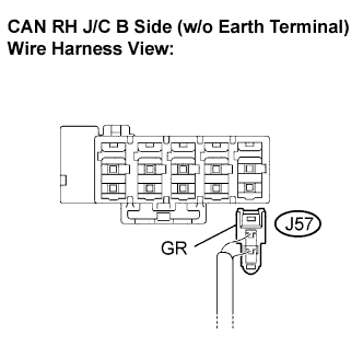 |
Disconnect the HV control ECU main bus line connector (J57) from the CAN RH J/C B side (w/o earth terminal).
 |
Measure the resistance according to the value(s) in the table below.
| Tester Connection | Condition | Specified Value |
| (CANH) - (CANL) | Disconnect the negative auxiliary battery cable | 108 to 132 Ω |
|
| ||||
| OK | |
| 14.CONNECT CONNECTOR |
Reconnect the HV control ECU main bus line connector (J57) to the CAN RH J/C B side (w/o earth terminal).
| NEXT | |
| 15.CHECK CAN MAIN BUS LINE FOR DISCONNECTION |
 |
Disconnect the HV control ECU connector (H30).
Measure the resistance according to the value(s) in the table below.
| Tester Connection | Condition | Specified Value |
| H30-25 (CANH) - H30-33 (CANL) | Disconnect the negative auxiliary battery cable | 108 to 132 Ω |
|
| ||||
| NG | ||
| ||
