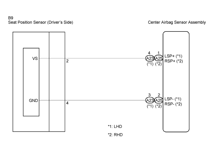
DTC B1153/25 Seat Position Airbag Sensor Circuit Malfunction |
| DTC No. | DTC Detecting Condition | Trouble Area |
| B1153/25 |
|
|
| 1.CHECK VEHICLE STEERING POSITION |
Check the vehicle steering position.
|
| ||||
| A | |
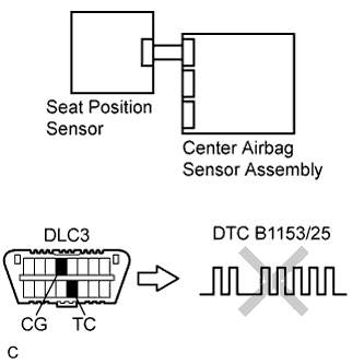
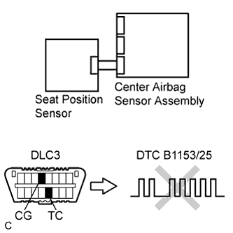
| 2.CHECK DTC |
 |
Turn the ignition switch to the ON position, and wait for at least 60 seconds.
Clear the DTCs stored in memory (Click here).
Turn the ignition switch to the LOCK position.
Turn the ignition switch to the ON position, and wait for at least 60 seconds.
Check the DTCs (Click here).
|
| ||||
| OK | ||
| ||
| 3.CHECK CONNECTION OF CONNECTORS |
Turn the ignition switch to the LOCK position.
Disconnect the negative (-) terminal cable from the battery, and wait for at least 90 seconds.
Check that the connectors are properly connected to the center airbag sensor assembly and the seat position sensor.
|
| ||||
| OK | |
| 4.CHECK FLOOR WIRE NO.2 (OPEN) |
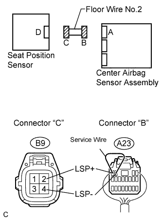 |
Disconnect the connectors from the center airbag sensor assembly and the seat position sensor.
Using a service wire, connect A23-4 (LSP+) and A23-3 (LSP-) of connector "B".
Measure the voltage according to the value(s) in the table below.
| Tester connection | Condition | Specified condition |
| B9-2 (LSP+) - B9-4 (LSP-) | Always | Below 1 V |
|
| ||||
| OK | |
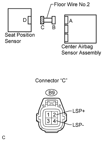
| 5.CHECK FLOOR WIRE NO.2 (SHORT TO B+) |
 |
Disconnect the service wire from connector "B".
Connect the negative (-) terminal cable to the battery, and wait for at least 2 seconds.
Turn the ignition switch to the ON position.
Measure the voltage according to the value(s) in the table below.
| Tester connection | Condition | Specified condition |
| B9-2 (LSP+) - Body ground | Ignition switch ON | Below 1 V |
| B9-4 (LSP-) - Body ground | Ignition switch ON | Below 1 V |
|
| ||||
| OK | |
| 6.CHECK FLOOR WIRE NO.2 (SHORT TO GROUND) |
|
Turn the ignition switch to the LOCK position.
Disconnect the negative (-) terminal cable from the battery, and wait for at least 90 seconds.
Measure the resistance according to the value(s) in the table below.
| Tester connection | Condition | Specified condition |
| B9-2 (LSP+) - Body ground | Always | 1 MΩ or higher |
| B9-4 (LSP-) - Body ground | Always | 1 MΩ or higher |
|
| ||||
| OK | |
| 7.CHECK SEAT POSITION SENSOR |
|
Connect the connectors to the seat position sensor and the center airbag sensor assembly.
Connect the negative (-) terminal cable to the battery, and wait for at least 2 seconds.
Turn the ignition switch to the ON position, and wait for at least 60 seconds.
Clear the DTCs stored in memory (Click here).
Turn the ignition switch to the LOCK position.
Turn the ignition switch to the ON position, and wait for at least 60 seconds.
Check the DTCs (Click here).
|
| ||||
| OK | ||
| ||
| 8.REPLACE SEAT POSITION SENSOR |
Turn the ignition switch to the LOCK position.
Disconnect the negative (-) terminal cable from the battery, and wait for at least 90 seconds.
Replace the seat position sensor (Click here).
| NEXT | |
| 9.CHECK CENTER AIRBAG SENSOR ASSEMBLY |
|
Connect the negative (-) terminal cable to the battery, and wait for at least 2 seconds.
Turn the ignition switch to the ON position, and wait for at least 60 seconds.
Clear the DTCs stored in memory (Click here).
Turn the ignition switch to the LOCK position.
Turn the ignition switch to the ON position, and wait for at least 60 seconds.
Check the DTCs (Click here).
|
| ||||
| OK | ||
| ||
| 10.CHECK DTC |
 |
Turn the ignition switch to the ON position, and wait for at least 60 seconds.
Clear the DTCs stored in memory (Click here).
Turn the ignition switch to the LOCK position.
Turn the ignition switch to the ON position, and wait for at least 60 seconds.
Check the DTCs (Click here).
|
| ||||
| OK | ||
| ||
| 11.CHECK CONNECTION OF CONNECTORS |
Turn the ignition switch to the LOCK position.
Disconnect the negative (-) terminal cable from the battery, and wait for at least 90 seconds.
Check that the connectors are properly connected to the center airbag sensor assembly and the seat position sensor.
|
| ||||
| OK | |
| 12.CHECK FLOOR WIRE (OPEN) |
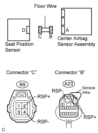 |
Disconnect the connectors from the center airbag sensor assembly and the seat position sensor.
Using a service wire, connect A25-1 (RSP+) and A25-2 (RSP-) of connector "B".
Measure the voltage according to the value(s) in the table below.
| Tester connection | Condition | Specified condition |
| B9-2 (RSP+) - B9-4 (RSP-) | Always | Below 1 V |
|
| ||||
| OK | |
| 13.CHECK FLOOR WIRE (SHORT TO B+) |
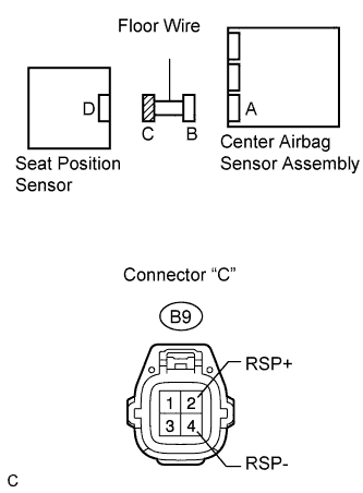 |
Disconnect the service wire from connector "B".
Connect the negative (-) terminal cable to the battery, and wait for at least 2 seconds.
Turn the ignition switch to the ON position.
Measure the voltage according to the value(s) in the table below.
| Tester connection | Condition | Specified condition |
| B9-2 (RSP+) - Body ground | Ignition switch ON | Below 1 V |
| B9-4 (RSP-) - Body ground | Ignition switch ON | Below 1 V |
|
| ||||
| OK | |
| 14.CHECK FLOOR WIRE (SHORT TO GROUND) |
|
Turn the ignition switch to the LOCK position.
Disconnect the negative (-) terminal cable from the battery, and wait for at least 90 seconds.
Measure the resistance according to the value(s) in the table below.
| Tester connection | Condition | Specified condition |
| B9-2 (RSP+) - Body ground | Always | 1 MΩ or higher |
| B9-4 (RSP-) - Body ground | Always | 1 MΩ or higher |
|
| ||||
| OK | |
| 15.CHECK SEAT POSITION SENSOR |
|
Connect the connectors to the seat position sensor and the center airbag sensor assembly.
Connect the negative (-) terminal cable to the battery, and wait for at least 2 seconds.
Turn the ignition switch to the ON position, and wait for at least 60 seconds.
Clear the DTCs stored in memory (Click here).
Turn the ignition switch to the LOCK position.
Turn the ignition switch to the ON position, and wait for at least 60 seconds.
Check the DTCs (Click here).
|
| ||||
| OK | ||
| ||
| 16.REPLACE SEAT POSITION SENSOR |
Turn the ignition switch to the LOCK position.
Disconnect the negative (-) terminal cable from the battery, and wait for at least 90 seconds.
Replace the seat position sensor (Click here).
| NEXT | |
| 17.CHECK CENTER AIRBAG SENSOR ASSEMBLY |
|
Connect the negative (-) terminal cable to the battery, and wait for at least 2 seconds.
Turn the ignition switch to the ON position, and wait for at least 60 seconds.
Clear the DTCs stored in memory (Click here).
Turn the ignition switch to the LOCK position.
Turn the ignition switch to the ON position, and wait for at least 60 seconds.
Check the DTCs (Click here).
|
| ||||
| OK | ||
| ||
