CAMSHAFT > INSTALLATION |
| 1. INSTALL CAMSHAFT SUB GEAR |
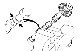 |
Clamp the camshaft in a vise on the hexagonal lobe.
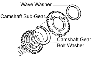 |
Install the camshaft gear bolt washer and the camshaft sub-gear.
Install the wave washer.
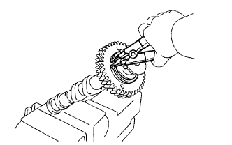 |
Using snap ring pliers, install the snap ring.
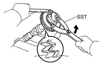 |
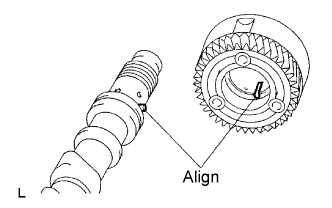
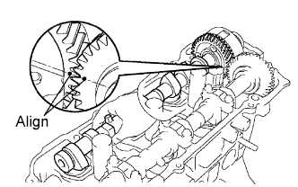
Using SST, align the holes of the camshaft main gear and sub-gear by turning camshaft sub-gear counterclockwise, and temporarily install a service bolt.
Align the gear teeth of the main gear and sub-gear, and tighten the service bolt.
| 2. INSTALL CAMSHAFT TIMING GEAR ASSEMBLY |
 |
Align the alignment pin with the groove and install the VVT-i on the camshaft.
Apply engine oil to the nut, the mounting surface of VVT-i and the screw threads.
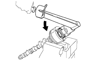 |
Using a 46 mm socket wrench, install and tighten a lock nut by turning it counterclockwise.
| 3. INSTALL NO.4 CAMSHAFT SUB-ASSEMBLY |
Apply new engine oil to the thrust portion and journal of the camshaft.
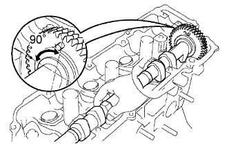 |
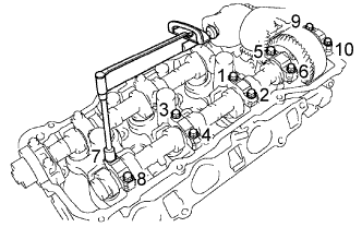
Place the No.4 camshaft at 90° angle of the timing mark (1-dot mark) on the cylinder head.
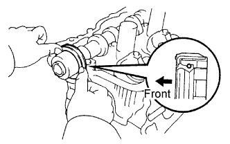
Apply MP grease to a new oil seal lip.
 |
Install the oil seal to the camshaft.
Remove any old packing material from the contact surface.
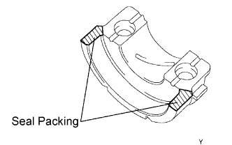 |
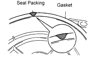
Apply seal packing to the No.1 bearing cap as shown in the illustration.
 |
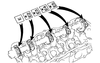
Install the 5 bearing caps in their proper locations.
Apply a light coat of engine oil to the threads of the bearing cap bolts.
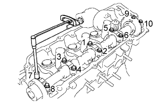 |
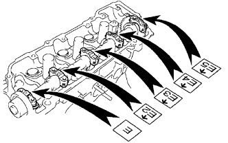
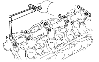
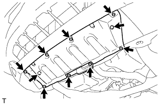
Using several steps, install and tighten the 10 bearing cap bolts uniformly in the sequence shown in the illustration.
| 4. INSTALL NO.3 CAMSHAFT SUB-ASSEMBLY |
Apply new engine oil to the thrust portion and journal of the camshaft.
 |
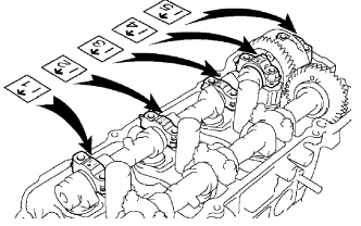
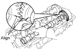
Align the timing marks (1-dot mark) of the camshaft drive gear with the mark on the driven gear.
Place the camshaft on the cylinder head.
 |
Install the 5 bearing caps in their proper locations.
Apply a light coat of engine oil to the threads of the bearing cap bolts.
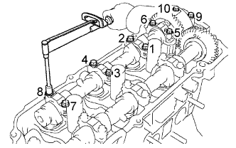 |
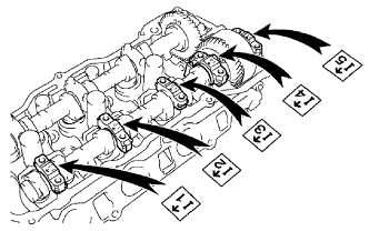
Using several steps, install and tighten the 10 bearing cap bolts uniformly in the sequence shown in the illustration.
Remove the service bolt.
| 5. INSTALL NO.2 CAMSHAFT |
Apply new engine oil to the thrust portion and journal of the camshaft.
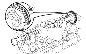 |
Place the No.2 camshaft at 90° angle of the timing mark (2-dot mark) on the cylinder head.
Apply MP grease to a new oil seal lip.
 |
Install the oil seal to the camshaft.
Remove any old packing material from the contact surface.
|
Apply seal packing to the No.1 bearing cap as shown in the illustration.
 |
Install the 5 bearing caps in their proper locations.
Apply a light coat of engine oil to the threads of the bearing cap bolts.
 |
Using several steps, tighten the 10 bearing cap bolts uniformly in the sequence shown in the illustration.
| 6. INSTALL CAMSHAFT |
Apply new engine oil to the thrust portion and journal of the camshaft.
 |
Align the timing marks (2-dot mark) of the camshaft drive gear with the mark on the driven gear.
Place the camshaft on the cylinder head.
 |
Install the 5 bearing caps in their proper locations.
Apply a light coat of engine oil to the threads of the bearing cap bolts.
 |
Using several steps, tighten the 10 bearing cap bolts uniformly in the sequence shown in the illustration.
Remove the service bolt.
| 7. INSTALL TIMING BELT NO.3 COVER |
Visually check for cracks and breaks on the gasket of the timing belt cover.
 |
If the timing belt cover gasket is needed to repair, follow the procedure below.
Repair the cracks and breaks by applying the seal packing to the damaged area.
If the timing belt cover gasket is needed to replace, follow the procedure below.
Using a screwdriver and gasket scraper, remove the remaining gasket.
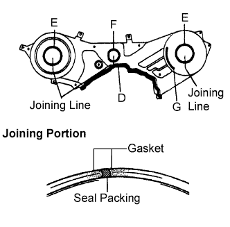 |
Remove the backing paper from a new gasket, and affix the gasket along the groove of the timing belt cover as shown in the illustration.
| Gasket | D | E | F | G |
| Length | 335 mm (13.19 in.) | 180 mm (7.09 in.) | 133 mm (5.24 in.) | 72 mm (2.83 in.) |
If there is a gap on the joint of the gasket, apply seal packing to close the gap.
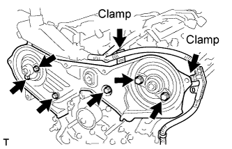 |
Install the timing belt cover No.3 with the 6 bolts.
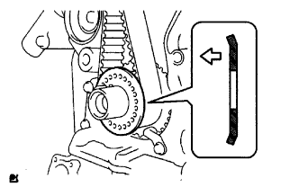
| 8. INSTALL CAMSHAFT TIMING PULLEY |
 |
Paying attention to the direction of the belt guide, install the camshaft timing pulley and tighten the bolt temporally.
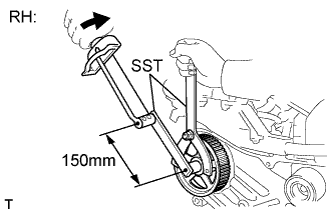 |
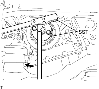
Using SST, tighten the RH pulley bolt.
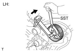 |
Using SST, tighten the LH pulley bolt.
| 9. INSTALL TIMING BELT IDLER SUB-ASSEMBLY NO.2 |
Install the timing belt idler sub-assembly No.2.
| 10. INSPECT TIMING BELT |
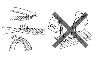 |
If there is premature parting:
If the belt teeth are cracked or damaged, check if either camshaft is locked.
If there is noticeable wear or cracks on the belt face, check if there are nicks on the side of the idler pulley lock and water pump.
If there is wear or damage to only one side of the belt, check the belt guide and the alignment of each pulley.
If there is noticeable wear on the belt teeth:
| 11. INSTALL TIMING BELT |
Remove any oil or water on the pulleys, and keep them clean.
Inspect the idler pulleys.
Check that the idler pulley turns smoothly.
Visually check the seal portion of the idler pulley for oil leakage.
Inspect the water pump.
Turn the pulley, and check that the water pump bearing moves smoothly and does not make any noise.
Visually check the drain hole for coolant leakage.
Temporarily install the crankshaft pulley bolt and washer to the crankshaft.
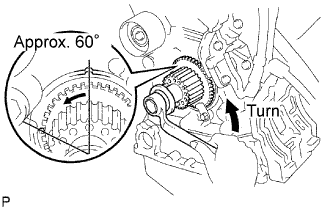 |
Turn the crankshaft counterclockwise by approximately 60°.
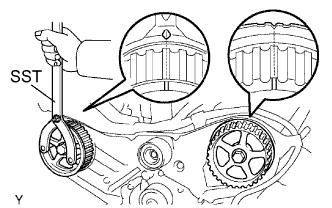 |
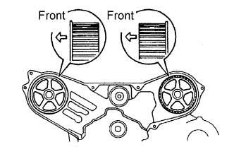
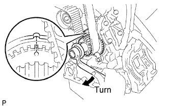
Using SST, turn the timing pulleys, and align the timing marks of the timing pulleys with the No.3 timing belt cover.
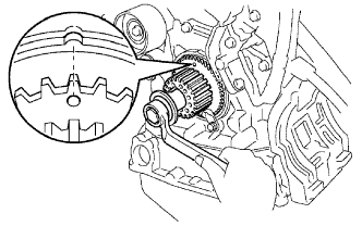 |
Turn the crankshaft, and align the timing mark of the crankshaft timing pulley with the oil pump body.
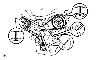 |
Face the front mark on the timing belt forward.
Align the installation mark on the timing belt with the timing mark of the crankshaft timing pulley.
Align the installation marks on the timing belt with the timing marks of the camshaft timing pulleys.
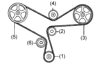 |
Install the timing belt in the following order.
| 1st | Crankshaft timing pulley |
| 2nd | Water pump pulley |
| 3rd | LH camshaft timing pulley |
| 4th | No.2 idler pulley |
| 5th | RH camshaft timing pulley |
| 6th | No.1 idler pulley |
| 12. INSTALL CHAIN TENSIONER ASSEMBLY NO.1 |
Set the timing belt tensioner upright on the press.
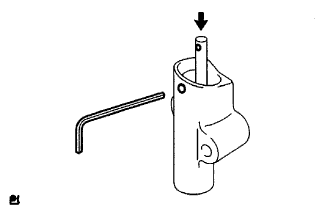 |
Slowly press in the push rod.
Align the holes of the push rod and housing, and pass a 1.5 mm hexagon wrench through the holes to keep the setting position of the push rod.
Release the press.
Temporarily install the tensioner with the 2 bolts. Alternately tighten the 2 bolts.
Remove the 1.5 mm hexagon wrench from the tensioner.
 |
Turn the crankshaft 2 revolutions slowly and align the timing mark of the crankshaft timing pulley with the oil pump body.
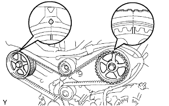 |
Check the timing marks of the RH and LH timing pulleys are aligned with the timing marks of the No.3 timing belt cover as shown in the illustration.
If the marks do not align, remove the timing belt and reinstall it.
Remove the crankshaft pulley bolt.
| 13. INSTALL TIMING BELT GUIDE NO.2 |
 |
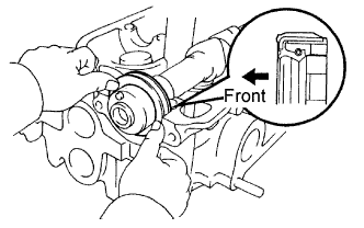
Install the timing belt guide with the cup side facing toward the engine front.
| 14. INSTALL ENGINE MOUNTING BRACKET RH |
 |
Install the engine mounting bracket RH with the 2 bolts and 2 nuts.
| 15. INSTALL TIMING BELT NO.2 COVER |
Visually check for cracks and breaks on the gasket of the timing belt cover.
If a trace of water is found in the visual check, replace the timing belt cover.
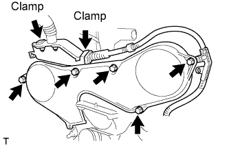 |
Install the timing belt cover with the 5 bolts.
Connect the 2 clamps.
| 16. INSTALL TIMING BELT NO.1 COVER |
Visually check for cracks and breaks on the gasket of the timing belt cover.
If a trace of water is found in the visual check, replace the timing belt cover.
Install the timing belt cover.
Install the engine wire protector cover to the timing belt No.3 cover.
| 17. INSTALL CRANKSHAFT PULLEY |
 |
Align the keyway of the pulley with the key located on the crankshaft and slide the pulley into place.
Using SST, install the pulley bolt.
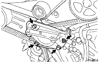
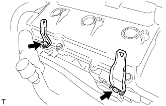
| 18. INSTALL ENGINE MOUNTING STAY NO.2 RH |
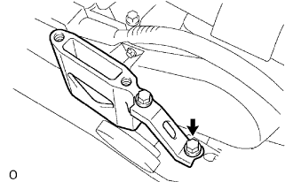 |
Install the engine mounting stay No.2 and the engine mounting bracket No.2 with the bolt.
| 19. INSTALL ENGINE MOVING CONTROL ROD |
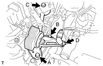 |
Temporarily tighten bolts B and C.
First tighten bolt A, bolt B, then bolt C in this order.
Tighten bolt D.
| 20. REMOVE AIR CLEANER BRACKET |
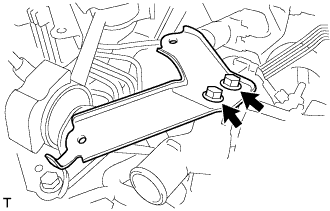 |
Install the 2 bolts and air cleaner bracket.
| 21. REMOVE RESERVOIR BRACKET |
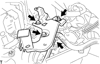 |
Install the 2 bolts, nut and reservoir bracket.
Connect the clamp.
| 22. REMOVE BRAKE MASTER CYLINDER RESERVOIR SUB-ASSEMBLY |
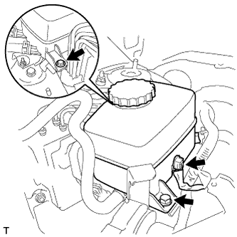 |
Install the 2 bolts and brake master cylinder reservoir to the bracket.
Connect the connector.
| 23. INSPECT VALVE CLEARANCE |
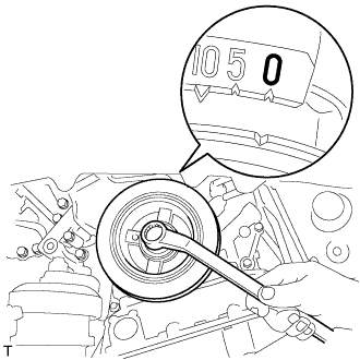 |
Turn the crankshaft pulley, and align the timing notch with the timing mark "0" of the No.1 timing belt cover.
Check that the valve lifters on the No.1 cylinder (IN and EX) are both loose.
If not, turn the crankshaft 1 revolution (360°) and align the mark as above.
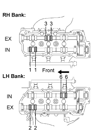 |
Check the valves indicated in the illustration.
Using a feeler gauge, measure the clearance between the valve lifter and the camshaft.
Record out-of-specification valve clearance measurements. They will be used later to determine the required replacement adjusting shim.
 |
Turn the crankshaft 2/3 of a revolution (240°), and check the valves indicated in the illustration.
Using a feeler gauge, measure the clearance between the valve lifter and the camshaft.
Record out-of-specification valve clearance measurements. They will be used later to determine the required replacement adjusting shim.
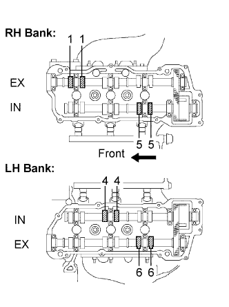 |
Turn the crankshaft 2/3 of a revolution (240°), and check the valves indicated in the illustration.
Using a feeler gauge, measure the clearance between the valve lifter and the camshaft.
Record out-of-specification valve clearance measurements. They will be used later to determine the required replacement adjusting shim.
| 24. ADJUST VALVE CLEARANCE |
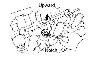 |
Turn the camshaft so that the cam lobe faces upward.
Turn the valve lifter with a screwdriver so that the notches are perpendicular to the camshaft.
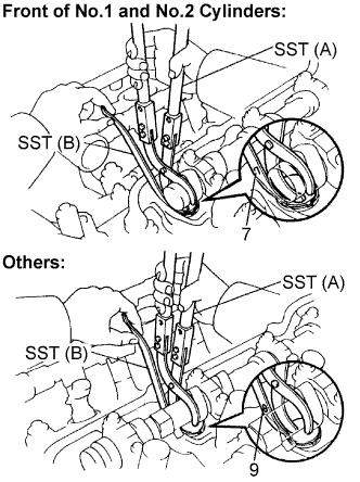 |
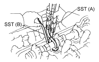
Using SST (A), press down the valve lifter and place SST (B) between the camshaft and valve lifter. Remove SST (A).
| SST (A) | 09248-05410 |
| SST (B) | 09248-05420 |
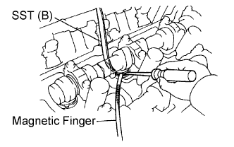 |
Using a screwdriver and magnetic finger, remove the adjusting shim.
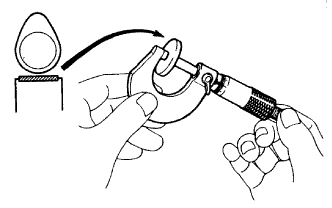 |
Using a micrometer, measure the thickness of the removed shim.
Calculate the thickness of a new shim so the valve clearance comes within the specified value.
| A | Thickness of new shim |
| B | Thickness of used shim |
| C | Measured valve clearance |
Select a new shim with a thickness as close as possible to the calculated values.
| EXAMPLE (Intake): Measured valve clearance = 0.45 mm (0.0177 in.) 0.45 mm (0.0177 in.) - 0.20 mm (0.0079 in.) = 0.25 mm (0.0098 in.) (Measured - Specification = Excess clearance) Used shim measurement = 2.80 mm (0.1102 in.) 0.25 mm (0.0098 in.) + 2.80 mm (0.1102 in.) = 3.05 mm (0.1201 in.) (Excess clearance + Used shim = Ideal new shim) Closest new shim = 3.05 mm (0.1201 in.) Select No.12 shim |
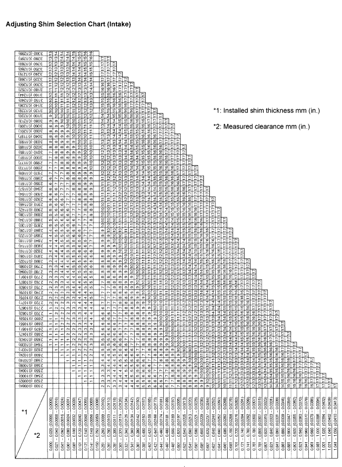
| Shim No. | Thickness | Shim No. | Thickness |
| 1 | 2.500 (0.0984) | 10 | 2.950 (0.1161) |
| 2 | 2.550 (0.1004) | 11 | 3.000 (0.1181) |
| 3 | 2.600 (0.1024) | 12 | 3.050 (0.1201) |
| 4 | 2.650 (0.1043) | 13 | 3.100 (0.1220) |
| 5 | 2.700 (0.1063) | 14 | 3.150 (0.1240) |
| 6 | 2.750 (0.1083) | 15 | 3.200 (0.1260) |
| 7 | 2.800 (0.1102) | 16 | 3.250 (0.1280) |
| 8 | 2.850 (0.1122) | 17 | 3.300 (0.1299) |
| 9 | 2.900 (0.1142) |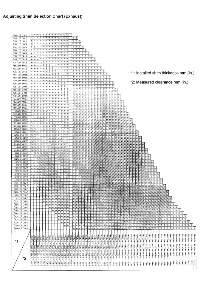
 |
Place a new adjusting shim on the valve lifter with imprinted number facing down.
Press down the valve lifter with SST (A), and remove SST (B).
Recheck the valve clearance.
| 25. INSTALL CYLINDER HEAD COVER SUB-ASSEMBLY |
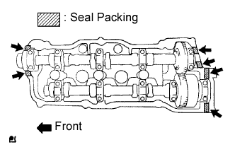 |
Apply seal packing to the cylinder head as shown in the illustration.
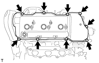 |
Install the cylinder head cover with the 9 bolts. Tighten the bolts uniformly in several steps.
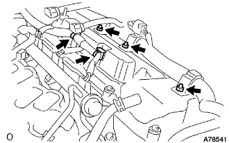 |
Install the engine wire harness with the 3 nuts and 2 clamps.
| 26. REMOVE CYLINDER HEAD COVER SUB-ASSEMBLY LH |
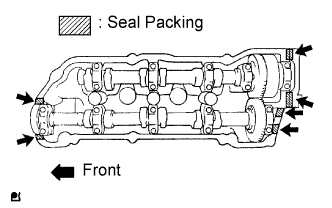 |
Apply seal packing to the cylinder head as shown in the illustration.
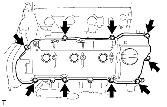 |
Install the cylinder head cover with the 9 bolts. Tighten the bolts uniformly in several steps.
 |
Install the 2 brackets with the 2 bolts.
 |
Install the 2 engine wire harness clamps.
 |
Using an E6 "torx" socket wrench, install the engine wire harness protector with the 2 bolts.
| 27. INSTALL IGNITION COIL ASSEMBLY |
| 28. INSTALL ENGINE MOUNTING STAY NO.2 RH |
|
Install the engine mounting stay No.2 and the engine mounting bracket No.2 with the bolt.
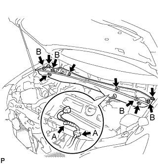
| 29. INSTALL ENGINE MOVING CONTROL ROD |
|
Temporarily tighten bolts B and C.
First tighten bolt A, bolt B, then bolt C in this order.
Tighten bolt D.
| 30. INSTALL AIR CLEANER BRACKET |
|
Install the 2 bolts and air cleaner bracket.
| 31. INSTALL RESERVOIR BRACKET |
|
Install the 2 bolts, nut and reservoir bracket.
Connect the clamp.
| 32. INSTALL BRAKE MASTER CYLINDER RESERVOIR SUB-ASSEMBLY |
|
Install the 2 bolts and brake master cylinder reservoir to the bracket.
Connect the connector.
| 33. CONNECT RADIATOR HOSE INLET |
| 34. INSTALL INTAKE AIR SURGE TANK |
Install a new gasket to the intake air surge tank.
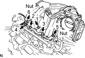 |
Using a socket hexagon wrench 8 mm, install the intake manifold with the 4 bolts and 2 nuts . Using several steps, tighten the bolts and nuts uniformly in the sequence shown in the illustration.
Connect the ground cable connector.
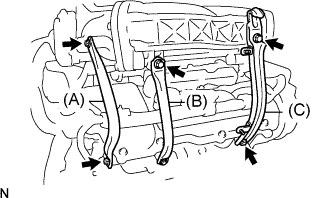 |
Install the surge tank stay No. 2 (A) with the 2 bolts.
Install the surge tank stay No. 1 (B) with the 2 bolts.
Install the engine hunger No. 1 (C) with the 2 bolts.
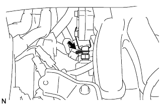 |
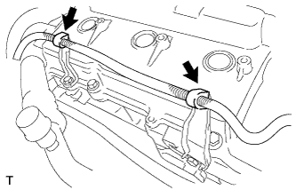
Connect the ventilation hose.
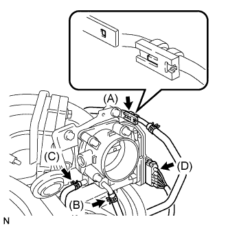 |
Connect the fuel vapor feed hose (A).
Connect the water by-pass hose No.3 (B).
Connect the water by-pass hose No.2 (C).
Connect the throttle motor connector (D).
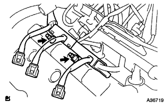
| 35. INSTALL EMISSION CONTROL VALVE SET |
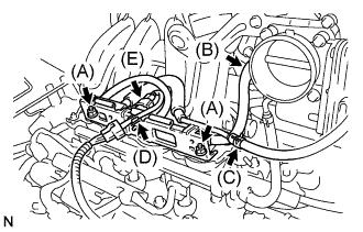 |
Install the emission control valve set with the 2 nuts (A).
Connect the fuel vapor feed hose No.2 (B).
Connect the fuel vapor feed hose No.1 (C).
Connect the wire harness clamp (D).
Connect the VSV connector (E).
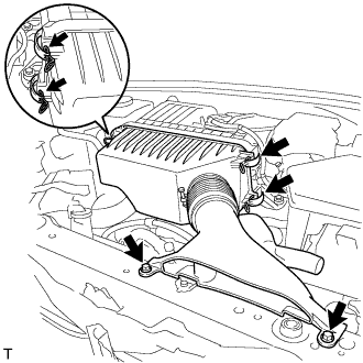
| 36. INSTALL AIR CLEANER CASE W/ RESONATOR |
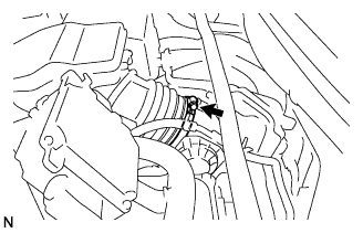 |
Install the air cleaner hose No.1 to the throttle body assembly with the hose clamp.
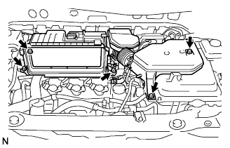 |
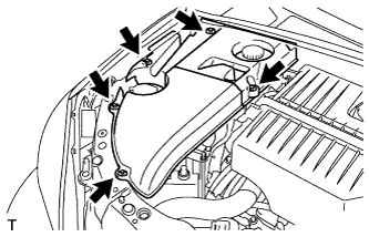
Install the air cleaner case w/ resonator with the 5 bolts.
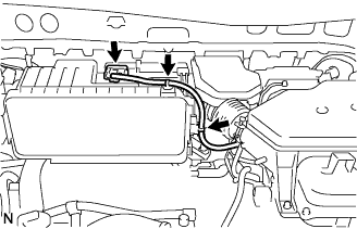 |
Connect the MAF meter connector.
Connect the 2 wire harness clamps to the air cleaner.
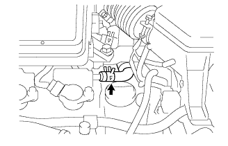 |
Connect the ventilation hose No.2.
| 37. INSTALL AIR CLEANER CAP W/ INLET |
Install the air cleaner filter element to the air cleaner case.
 |
Install the 2 bolts, 4 clamps and air cleaner cap w/ inlet.
| 38. REMOVE COOL AIR INTAKE DUCT SEAL |
Install the 4 clips and cool air intake duct seal.
| 39. REMOVE BATTERY CARRIER SUB-ASSEMBLY |
 |
Install the 5 bolts and battery carrier.
| 40. REMOVE BATTERY |
Install the battery clamp and battery.
| 41. INSTALL COWL TOP PANEL SUB-ASSEMBLY OUTER |
Remove the 4 shock absorber nuts.
 |
Install the 4 bolts, 2 nuts and cowl top panel sub-assembly.
Install the 4 shock absorber nuts (B).
Install the wire harness clamp and grommet (A).
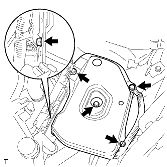
| 42. INSTALL WINDSHIELD WIPER MOTOR AND LINK ASSEMBLY |
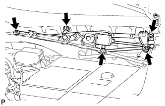 |
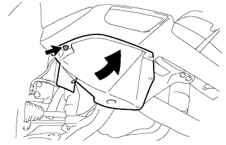
Install the windshield wiper motor and link assembly with the 5 bolts.
Connect the connector.
| 43. REMOVE COWL TOP VENTILATOR LOUVER SUB-ASSEMBLY |
| 44. INSTALL FRONT WIPER ARM AND BLADE ASSEMBLY LH |
 |
Operate the front wiper, and stop the front wiper motor at the automatic stop position.
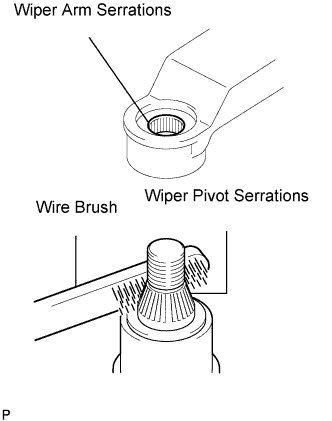
Clean the wiper arm serrations.
Clean the wiper pivot serrations with a wire brush (when reinstalling).
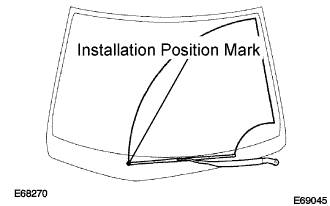 |
Install the front wiper arm and blade assembly LH with the nut at the position as shown in the illustration.
| 45. INSTALL FRONT WIPER ARM AND BLADE ASSEMBLY RH |
|
Clean the wiper arm serrations.
Clean the wiper pivot serrations with a wire brush (when reinstalling).
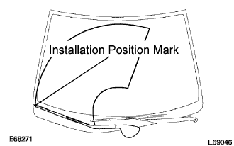 |
Install the front wiper arm and blade assembly RH with the 2 nuts at the position as shown in the illustration.
Operate the front wipers while spraying water or washer fluid on the windshield.
Make sure that the wipers function properly and there is no interference with the vehicle body.
| 46. REMOVE FRONT FENDER APRON SEAL RH |
 |
Install the 2 bolts, clip and fender apron seal RH.
| 47. REMOVE FRONT FENDER SPLASH SHIELD SUB-ASSEMBLY RH |
 |
Install the fender splash shield with the screw.
| 48. REMOVE ENGINE UNDER COVER NO.1 |
 |
Install the 6 bolts, 2 screws, 2 clips and engine under cover.
| 49. INSTALL FRONT WHEEL RH |
| 50. ADD ENGINE OIL |
| 51. ADD COOLANT |
Tighten the lower drain plug of the radiator.
Loosen the upper drain plug of the radiator.
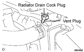 |
Install a vinyl tube to the vent plug located on the upper drain plug.
Fill the radiator with engine coolant until the vinyl tube is filled with the coolant.
Tighten the upper drain plug.
Install the radiator cap securely.
Fill the radiator reservoir tank with coolant.
Warm up the engine.
Stop the engine and wait until the coolant cools down.
Remove the radiator cap and check the coolant level inside the radiator.
If the coolant level is below the full level, perform the steps from (a) through (j) and repeat the operation until the coolant level stays the full level.
Recheck the coolant level inside the radiator reservoir tank. If it is below the full level, add the coolant.
| 52. CHECK FOR ENGINE COOLANT LEAKS |
 |
Fill the radiator with coolant and attach a radiator cap tester.
Warm up the engine.
Using a radiator cap tester, increase the pressure inside the radiator to 118 kPa (1.2 kgf*cm, 17 psi), and check that the pressure does not drop.
If the pressure drops, check the hoses, radiator and water pump for leaks. If no external leaks are found, check the heater core, cylinder block and cylinder head.
| 53. CHECK FOR ENGINE OIL LEAKS |
| 54. INSPECT IGNITION TIMING |
Set the vehicle to inspection mode (Click here).
Warm up the engine.
When using the intelligent tester:
Connect the intelligent tester (with CAN VIM) to the DLC3.
Enter DATA LIST MODE on the intelligent tester.
Check that the ignition timing advances immediately when the engine speed is increased.
 |
When not using the intelligent tester:
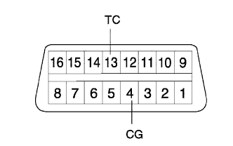
Using SST, connect terminals 13 (TC) and 4 (CG) of the DLC3.
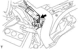 |
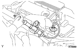
Pull out the red-colored wire harness as shown in the illustration.
Connect the tester terminal of the timing light to the engine.
Inspect ignition timing at idle.
Disconnect terminals 13 (TC) and 4 (CG) of the DLC3.
Inspect ignition timing at idle.
Confirm that the ignition timing advances when the engine rpm is increased.
Remove the timing light.
| 55. INSPECT IDLE SPEED |
Set the vehicle to inspection mode (Click here).
Warm up the engine.
Connect the intelligent tester (with CAN VIM) to the DLC3.
Enter DATA LIST MODE on the intelligent tester.
| 56. PERFORM INITIALIZATION |
Some system need initialization when reconnecting the battery cable. (Click here)
| 57. REMOVE ENGINE ROOM COVER SIDE |
 |
Install the 5 clips and engine room cover side
| 58. REMOVE ENGINE ROOM SIDE LH COVER |
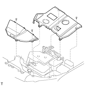 |
Fit the clips and install the engine room side LH cover.
