ENGINE ASSEMBLY > INSTALLATION |
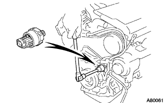
| 1. INSTALL KNOCK CONTROL SENSOR |
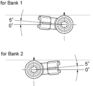 |
Install the 2 knock sensors so that it is horizontal as shown in the illustration. Then install the 2 bolts.
 |
Connect the 2 knock sensor connectors.
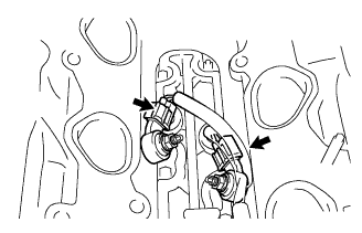
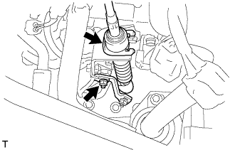
| 2. INSTALL ENGINE OIL PRESSURE SWITCH ASSEMBLY |
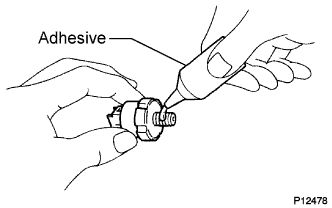 |
Apply adhesive to 2 or 3 threads of the oil pressure switch.
 |
Using a deep socket wrench 24 mm, install the oil pressure switch.
| 3. INSTALL THERMOSTAT |
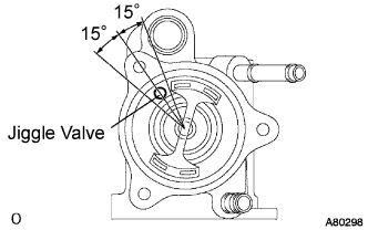 |
Install a new gasket to the thermostat.
Align the jiggle valve of the thermostat and water inlet, and insert the thermostat in the water inlet housing.
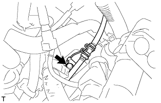
| 4. INSTALL WATER INLET |
 |
Install the 3 nuts and the water inlet with the 3 nuts.
| 5. INSTALL WATER INLET PIPE |
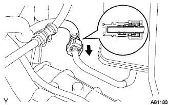
 |
Install a new O-ring to the water inlet pipe.
Apply soapy water to the O-ring.
Connect the water inlet pipe to the water inlet.
Install the bolt which is used to fix the water inlet pipe to the cylinder head with the bolt.
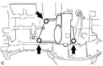
| 6. INSTALL INTAKE AIR CONNECTOR BRACKET NO.2 |
 |
Install the intake air connector bracket No.2 with the 2 bolts. Using several steps, tighten the bolts uniformly in the sequence shown in the illustration.
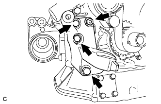
| 7. INSTALL COMPRESSOR MOUNTING BRACKET NO.1 |
Temporarily install the mounting bracket with the 4 bolts.
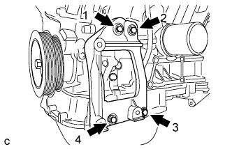 |
Install the mounting bracket by tightening the 4 bolts in the order shown in the illustration.
| 8. INSTALL ENGINE MOUNTING STAY BRACKET |
 |
Install the 3 bolts, nut and engine mounting stay bracket.
| 9. INSTALL ENGINE MOUNTING BRACKET RH |
 |
Install the 3 bolts and engine mounting bracket RH.
| 10. INSTALL ENGINE MOUNTING BRACKET REAR |
 |
Install the 3 bolts and engine mounting bracket rear.
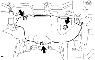
| 11. INSTALL MANIFOLD STAY NO.2 |
Install the 2 bolts and manifold stay No.2.
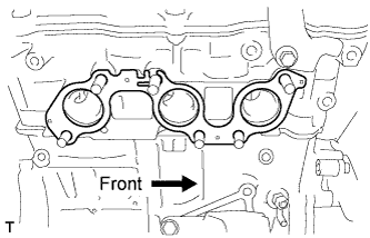
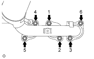
| 12. INSTALL EXHAUST MANIFOLD CONVERTER SUB-ASSEMBLY NO.2 |
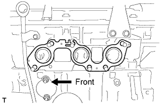 |
Install a new gasket as shown in the illustration.
 |
Install the exhaust manifold converter No.2 with the 6 nuts and bolt. Using several steps, tighten the nuts uniformly in the sequence shown in the illustration.
Retighten nuts 1 and 2 shown in the illustration.
| 13. INSTALL EXHAUST MANIFOLD HEAT INSULATOR NO.2 |
 |
Install the 2 bolts and exhaust manifold heat insulator No.2.
| 14. INSTALL MANIFOLD CONVERTER INSULATOR NO.3 |
 |
Install the bolt, nut and manifold converter insulator No.3.
| 15. INSTALL IGNITION COIL ASSEMBLY |
| 16. INSTALL WATER OUTLET |
Install 2 new gaskets to the 2 cylinder heads.
Install the water outlet together with water by-pass hose No.1 and unlock the hose clamp.
Tighten the 2 bolts, 2 nuts and 2 washers.
Install the clamp.
Connect the engine coolant temperature sensor connector.
Connect the radiator hose inlet.
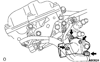
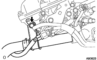
| 17. INSTALL INTAKE MANIFOLD |
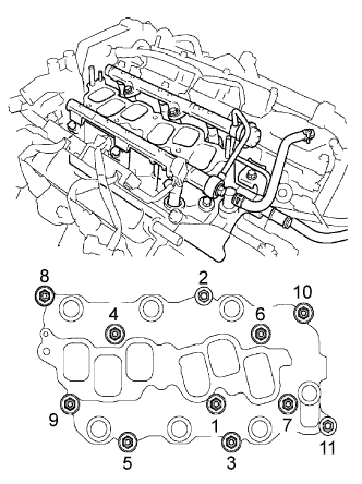 |
Install the intake manifold with the 9 bolts, 2 nuts and 2 washers. Using several steps, tighten the bolts and nuts uniformly in the sequence shown in the illustration.
Retighten the water outlet mounting bolts and nuts.
Install the ground cable with the nut.
Connect the heater inlet water hose.
| 18. INSTALL INTAKE AIR SURGE TANK |
Install a new gasket to the intake air surge tank.
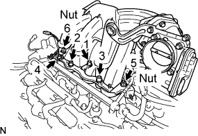 |
Using a socket hexagon wrench 8 mm, install the intake manifold with the 4 bolts and 2 nuts . Using several steps, tighten the bolts and nuts uniformly in the sequence shown in the illustration.
Connect the ground cable connector.
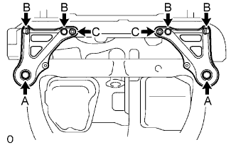
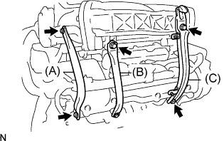 |
Install the surge tank stay No. 2 (A) with the 2 bolts.
Install the surge tank stay No. 1 (B) with the 2 bolts.
Install the engine hunger No. 1 (C) with the 2 bolts.
 |
Connect the ventilation hose.
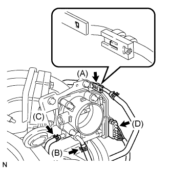 |
Connect the fuel vapor feed hose (A).
Connect the water by-pass hose No.3 (B).
Connect the water by-pass hose No.2 (C).
Connect the throttle motor connector (D).
| 19. INSTALL EMISSION CONTROL VALVE SET |
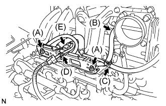 |
Install the emission control valve set with the 2 nuts (A).
Connect the fuel vapor feed hose No.2 (B).
Connect the fuel vapor feed hose No.1 (C).
Connect the wire harness clamp (D).
Connect the VSV connector (E).
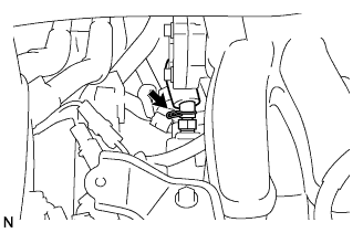
| 20. INSTALL ENGINE HANGER NO.2 |
 |
Install the No.2 engine hanger in the correct direction shown in the illustration.
| 21. REMOVE ENGINE STAND |
| 22. INSTALL FLYWHEEL SUB-ASSEMBLY |
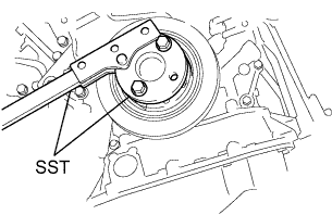 |
Using SST, hold the crankshaft.
Clean the bolts and bolt holes.
Apply adhesive to 2 or 3 threads of the bolts.
Install the flywheel on the crankshaft.
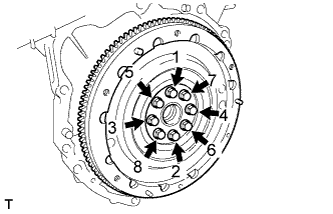 |
Using several steps, install and tighten the 8 bolts uniformly in the sequence shown in the illustration.
| 23. INSTALL TRANSMISSION INPUT DAMPER ASSEMBLY |
|
Using SST, hold the crankshaft.
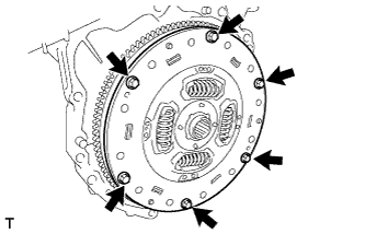 |
Install the 6 bolts and transmission input damper.
| 24. INSTALL HYBRID VEHICLE TRANSAXLE ASSEMBLY |
Make sure that the knock pins are installed on the engine.
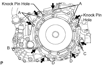 |
Install the hybrid vehicle transaxle and the 8 bolts shown in the illustration to the engine.
| Bolt | Installation direction | Diameter | Bolt length |
| A | From transaxle to engine | 12 mm (0.47 in.) | 55 mm (2.17 in.) |
| B | From engine to transaxle | 10 mm (0.39 in.) | 55 mm (2.17 in.) |
| C | From transaxle to engine | 12 mm (0.47 in.) | 55 mm (2.17 in.) |
| D | From engine to transaxle | 10 mm (0.39 in.) | 33 mm (1.30 in.) |
| 25. INSTALL ENGINE MOUNTING BRACKET FRONT |
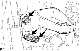 |
Install the engine mounting bracket front with the 3 bolts.
| 26. INSTALL FLYWHEEL HOUSING UNDER COVER |
 |
Install the flywheel housing under cover with the 2 bolts.
| 27. INSTALL FRONT DRIVE SHAFT ASSEMBLY LH |
Install a new drive shaft hole snap ring.
Coat the spline of the inboard joint shaft assembly with ATF.
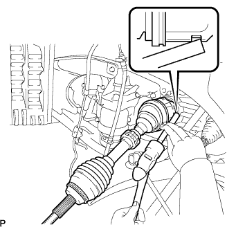 |
Align the shaft splines and install the drive shaft assembly with a brass bar and a hammer.
| 28. INSTALL FRONT DRIVE SHAFT ASSEMBLY RH |
Coat the spline of the inboard joint shaft assembly with ATF.
Align the shaft splines and install the drive shaft assembly.
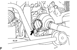 |
Using pliers, install a new bearing bracket hole snap ring.
 |
Install a new bolt to the drive shaft bearing bracket.
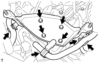
| 29. INSTALL FRONT FRAME ASSEMBLY |
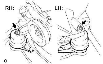 |
Install the engine mounting insulators RH and LH with the 2 nuts.
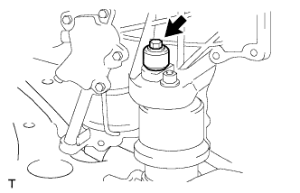
 |
Install the engine mounting insulator FR with the nut.
 |
Install the engine mounting insulator RR with the 2 bolts.
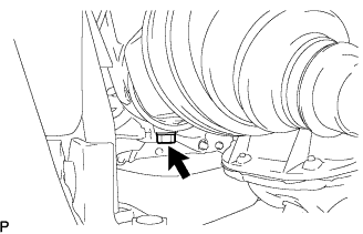
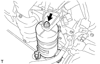
| 30. INSTALL HV TRANSAXLE MASS DAMPER |
 |
Install the bolt and transaxle mass damper.
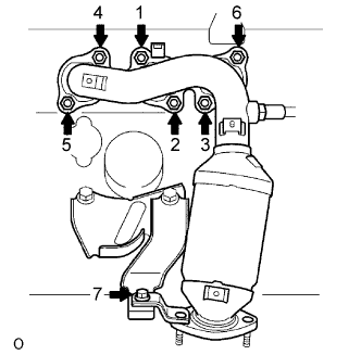
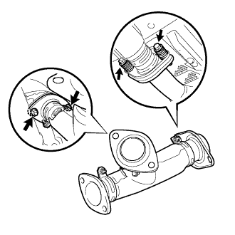
| 31. INSTALL EXHAUST MANIFOLD SUB-ASSEMBLY RH |
 |
Install a new gasket as shown in the illustration.
 |
Install a new gasket and the exhaust manifold RH with the 6 nuts. Using several steps, tighten the nuts uniformly in the sequence shown in the illustration.
Retighten nuts 1 and 2 shown in the illustration.
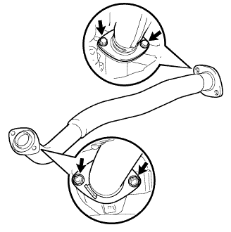
| 32. INSTALL MANIFOLD STAY |
Temporarily install the manifold stay to the exhaust manifold and transaxle.
Fully tighten the 2 bolts.
| 33. INSTALL EXHAUST MANIFOLD HEAT INSULATOR NO.1 |
 |
Install the 3 bolts and exhaust manifold heat insulator No.1.
| 34. INSTALL ENGINE WIRE |
| 35. INSTALL ENGINE ASSEMBLY WITH TRANSAXLE |
 |
Set the engine assembly with transaxle on the engine lifter.
Install the engine assembly to the vehicle.
Install the frame side rail plates RH and LH with the 6 bolts and 2 nuts.
 |
Install the front suspension member brace rear RH and LH with the 6 bolts and 2 nuts.
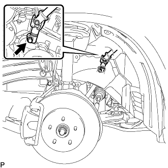
| 36. CONNECT STEERING INTERMEDIATE SHAFT SUB-ASSEMBLY |
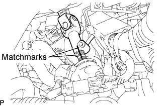 |
Align matchmarks on the steering intermediate shaft sub-assembly and the power steering link assembly.
 |
Install the bolt.
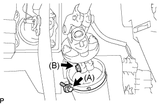 |
Tighten the bolt (B).
Install the clamp to the steering column hole shield and tighten the bolt (A).
| 37. INSTALL FRONT AXLE ASSEMBLY LH |
Install the drive shaft assembly LH to the front axle assembly LH.
| 38. INSTALL FRONT AXLE ASSEMBLY RH |
| 39. INSTALL FRONT SUSPENSION ARM SUB-ASSEMBLY LOWER NO.1 LH |
 |
Install the lower ball joint to the front suspension arm sub-assembly lower with the bolt and 2 nuts.
| 40. INSTALL FRONT SUSPENSION ARM SUB-ASSEMBLY LOWER NO.1 RH |
| 41. CONNECT TIE ROD END SUB-ASSEMBLY LH |
Connect the tie rod assembly LH to the steering knuckle with the nut.
Install a new cotter pin.
| 42. CONNECT TIE ROD END SUB-ASSEMBLY RH |
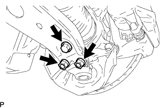
| 43. INSTALL SPEED SENSOR FRONT LH |
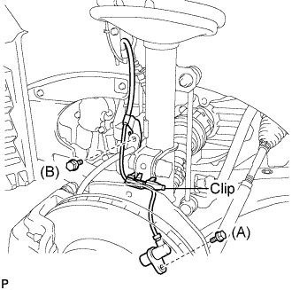 |
Install the speed sensor to the steering knuckle with the bolt.
Install the flexible hose and the speed sensor to the shock absorber with the bolt and set the clip of sensor on the knuckle.
| 44. INSTALL SPEED SENSOR FRONT RH |
| 45. INSTALL FRONT AXLE HUB LH NUT |
Using a socket wrench (30 mm), install a new axle hub nut.
| 46. INSTALL FRONT AXLE HUB RH NUT |
| 47. INSTALL FRONT STABILIZER LINK ASSEMBLY LH |
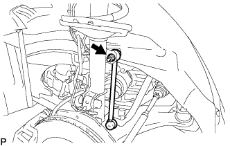 |
Install the front stabilizer link assembly with the nut.
| 48. INSTALL FRONT STABILIZER LINK ASSEMBLY RH |
| 49. INSTALL EXHAUST PIPE SUB-ASSEMBLY FRONT NO.3 |
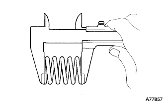 |
Using vernier calipers, measure the free length of the compression spring.
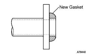 |
Install a new gasket to the exhaust pipe front No. 3 as shown in the illustration.
 |
Install 2 new gaskets and the exhaust pipe front No. 3 with the 2 bolts and 2 new nuts.
Connect the heated oxygen sensor connector.
| 50. INSTALL EXHAUST PIPE ASSEMBLY FRONT |
 |
Install 2 new gaskets and the exhaust pipe front No. 3 with the 2 bolts and 2 new nuts.
Connect the heated oxygen sensor connector.
| 51. CONNECT WIRE HARNESS |
Connect the power steering link connector and clamp.
Install the ground cable.
| 52. CONNECT ENGINE WIRE |
Install the 2 nuts and pull in the engine wire harness.
Connect the engine wire harness to the ECM and the junction block.
Install the body ground and connector.
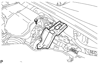
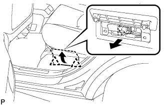
| 53. INSTALL GLOVE COMPARTMENT DOOR ASSEMBLY |
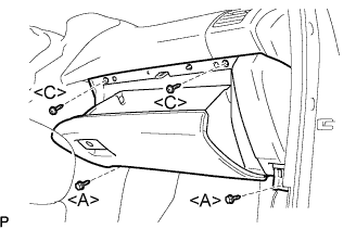 |
Connect the connectors.
Install the 2 bolts <A>, the 2 screws <C>, and the glove compartment door assembly.
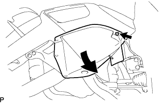
| 54. INSTALL INSTRUMENT PANEL NO.2 UNDER COVER SUB-ASSEMBLY |
 |
Connect the connectors.
Engage the 3 claws and install the instrument panel No.2 under cover sub-assembly.
| 55. CONNECT WATER HOSE |
| 56. INSTALL HEATER WATER PUMP ASSEMBLY |
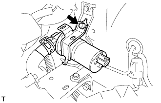 |
Install the bolt and heater water pump assembly.
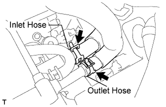
| 57. CONNECT OIL COOLER INLET TUBE SUB-ASSEMBLY |
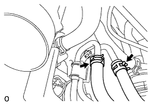 |
Using pliers, grip the claws of the clip and slide the clip to connect the oil cooler inlet tube.
| 58. CONNECT OIL COOLER OUTLET TUBE SUB-ASSEMBLY |
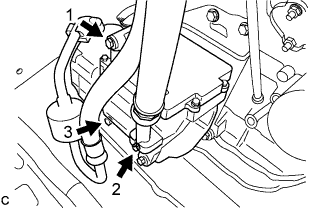
| 59. CONNECT RADIATOR HOSE INLET |
| 60. CONNECT RADIATOR HOSE OUTLET |
| 61. CONNECT HEATER WATER INLET HOSE |
 |
Using pliers, grip the claws of the clip and slide the clip to connect the heater water inlet hose.
| 62. CONNECT HEATER WATER OUTLET HOSE |
| 63. CONNECT FUEL PIPE SUB-ASSEMBLY NO.1 |
 |
Align the connector with the pipe, then push in the connector to the pipe until it makes a "click" sound to connect the fuel tube sub-assembly to the fuel delivery pipe.
Install the EFI fuel pipe clamp.
| 64. INSTALL TRANSMISSION CONTROL CABLE ASSEMBLY |
 |
Install the control cable to the transaxle with the bolt.
 |
Install the control shaft lever with the nut.
Install the control cable and a new clip to the bracket.
| 65. INSTALL INVERTER BRACKET NO.1 |
 |
Install the 4 bolts and inverter bracket.
Install the harness clamp and hose clamp.
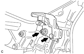
| 66. INSTALL COMPRESSOR W/ MOTOR ASSEMBLY |
Temporarily install the compressor and magnetic clutch with the 3 bolts.
 |
Install the compressor and magnetic clutch by tightening the 3 bolts in the order shown in the illustration.
Connect the 2 connectors.
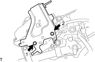
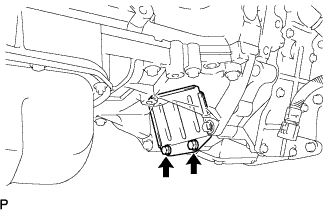
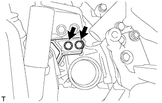
| 67. INSTALL ENGINE MOUNTING STAY NO.2 RH |
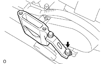 |
Install the engine mounting stay No.2 and the engine mounting bracket No.2 with the bolt.
| 68. INSTALL ENGINE MOVING CONTROL ROD |
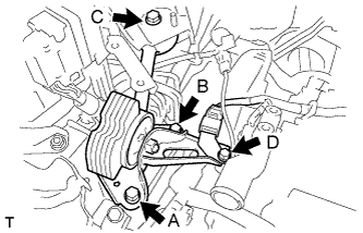 |
Temporarily tighten bolts B and C.
First tighten bolt A, bolt B, then bolt C in this order.
Tighten bolt D.
| 69. INSTALL AIR CLEANER BRACKET |
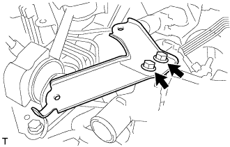 |
Install the 2 bolts and air cleaner bracket.
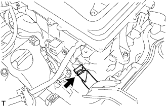
| 70. INSTALL RESERVOIR BRACKET |
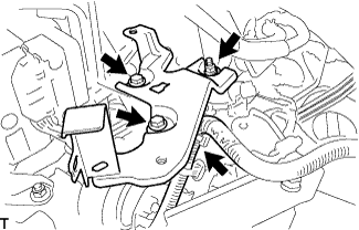 |
Install the 2 bolts, nut and reservoir bracket.
Connect the clamp.
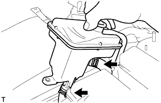
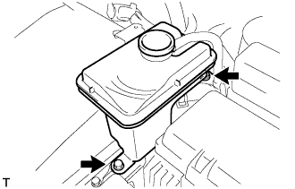
| 71. INSTALL BRAKE MASTER CYLINDER RESERVOIR SUB-ASSEMBLY |
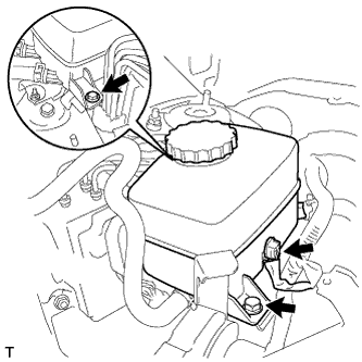 |
Install the 2 bolts and brake master cylinder reservoir to the bracket.
Connect the connector.
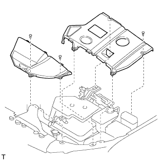
| 72. INSTALL W/ CONVERTER INVERTER ASSEMBLY |
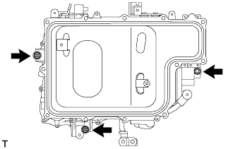 |
Install the w/ converter inverter assembly with the 2 nuts and bolt.
| 73. INSTALL INVERTER BRACKET NO.4 |
 |
Install the inverter bracket No.4 with the 2 bolts.
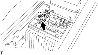
| 74. INSTALL ENGINE ROOM RELAY BLOCK ASSEMBLY |
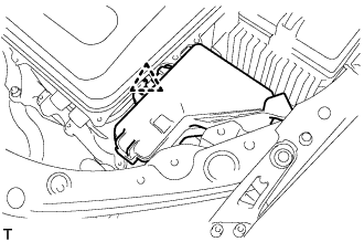 |
Install the engine room relay block assembly.
| 75. REMOVE INVERTER COVER |
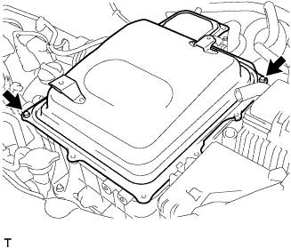 |
Remove the 2 bolts and inverter cover to the w/ converter inverter assembly.
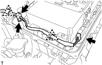
| 76. INSTALL NO.3 WIRE FRAME |
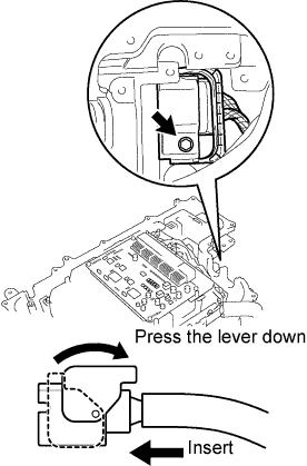 |
After connecting the connector, press the lever down to connect the No.3 wire frame and install the bolt to the w/ converter inverter assembly.
 |
Connect the No.3 wire frame (high voltage cable of the rear motor) with the 5 bolts to the w/ converter inverter assembly.
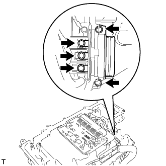
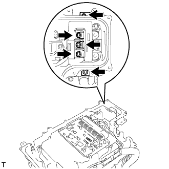
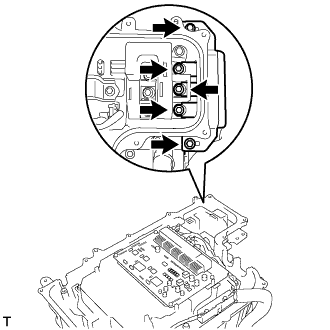
| 77. INSTALL MG ECU CONNECTOR |
 |
Connect the 2 connectors and 2 grommets to the w/ converter inverter assembly.
| 78. CONNECT HIGH VOLTAGE CABLE OF FRONT MOTOR |
 |
Connect the high voltage cable of the Generator with the 5 bolts to the w/ converter inverter assembly.
 |
Connect the high voltage cable of the Motor with the 5 bolts to the w/ converter inverter assembly.
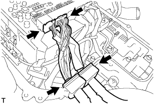
| 79. INSTALL ENGINE WIRE NO.4 |
 |
Connect the engine wire No.4 with the connector, clamp and grommet to the w/ converter inverter assembly.
Connect the engine wire No.4 with the bolt to the w/ converter inverter assembly.
| 80. CHECK HIGH VOLTAGE CABLE CONNECTION |
 |
Check that each connector and terminal is firmly installed.
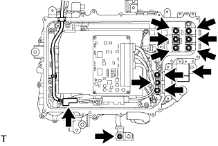
| 81. INSTALL INVERTER COVER |
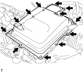 |
Install the inverter cover with the 12 bolts to the w/ converter inverter assembly.
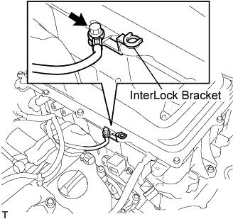 |
Install the interlock bracket with the bolt to the w/ converter inverter assembly.
| 82. INSTALL POWER STEERING ECU BRACKET |
 |
Install the power steering ECU bracket with the bolt to the w/ converter inverter assembly.
| 83. CONNECT WATER HOSE |
 |
Connect the water hose with the clamp to the w/ converter inverter assembly.
| 84. INSTALL INVERTER RESERVE TANK SUB-ASSEMBLY |
 |
Connect the 2 water hoses with the 2 clamps to the inverter reserve tank sub-assembly.
 |
Install the inverter reserve tank with the 2 bolts to the w/ converter inverter assembly.
| 85. CONNECT ENGINE ROOM WIRE NO.2 |
 |
Connect the engine room wire No.2 with the nut.
| 86. CONNECT CIRCUIT BREAKER SENSOR NO.1 |
 |
Connect the circuit breaker sensor No.1 connector.
| 87. INSTALL POWER STEERING ECU ASSEMBLY |
 |
Install the power steering ECU assembly with the 2 bolts.
 |
Connect the 2 wire harness clamps to the power steering ECU assembly.
 |
Connect the 2 power steering ECU assembly connectors and securely lock the connectors.
 |
Install the ground cable terminal to the power steering ECU assembly with the bolt.
| 88. INSTALL INVERTER BRACKET NO.5 |
 |
Install the inverter bracket No.5 with the bolt.
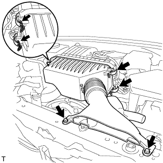
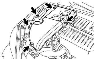
| 89. INSTALL AIR CLEANER CASE W/ RESONATOR |
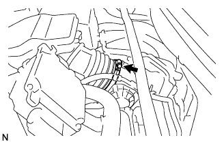 |
Install the air cleaner hose No.1 to the throttle body assembly with the hose clamp.
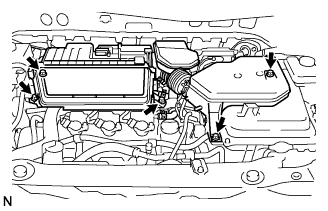 |
Install the air cleaner case w/ resonator with the 5 bolts.
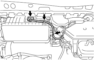 |
Connect the MAF meter connector.
Connect the 2 wire harness clamps to the air cleaner.
 |
Connect the ventilation hose No.2.
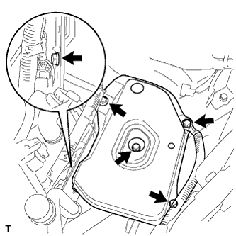
| 90. INSTALL AIR CLEANER CAP W/ INLET |
Install the air cleaner filter element to the air cleaner case.
 |
Install the 2 bolts, 4 clamps and air cleaner cap w/ inlet.
| 91. INSTALL COOL AIR INTAKE DUCT SEAL |
Install the 4 clips and cool air intake duct seal.
| 92. INSTALL BATTERY CARRIER SUB-ASSEMBLY |
 |
Install the 5 bolts and battery carrier.
| 93. INSTALL BATTERY |
Install the battery clamp and battery.
| 94. INSTALL SERVICE PLUG GRIP |
 |
Wear insulation gloves, then insert the service plug.
Push down on the grip to lock.
Close the battery service hole cover.
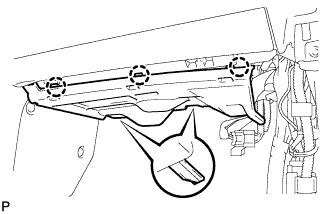
| 95. INSTALL COWL TOP PANEL SUB-ASSEMBLY OUTER |
Remove the 4 shock absorber nuts.
 |
Install the 4 bolts, 2 nuts and cowl top panel sub-assembly.
Install the 4 shock absorber nuts (B).
Install the wire harness clamp and grommet (A).
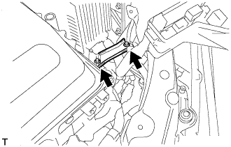
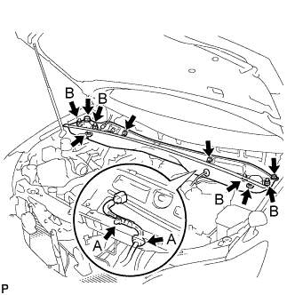
| 96. INSTALL WINDSHIELD WIPER MOTOR AND LINK ASSEMBLY |
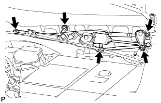 |
Install the windshield wiper motor and link assembly with the 5 bolts.
Connect the connector.
| 97. INSTALL COWL TOP VENTILATOR LOUVER SUB-ASSEMBLY |
| 98. INSTALL FRONT WIPER ARM AND BLADE ASSEMBLY LH |
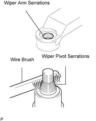 |
Operate the front wiper, and stop the front wiper motor at the automatic stop position.
Clean the wiper arm serrations.
Clean the wiper pivot serrations with a wire brush (when reinstalling).
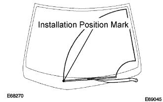 |
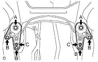
Install the front wiper arm and blade assembly LH with the nut at the position as shown in the illustration.
| 99. INSTALL FRONT WIPER ARM AND BLADE ASSEMBLY RH |
|
Clean the wiper arm serrations.
Clean the wiper pivot serrations with a wire brush (when reinstalling).
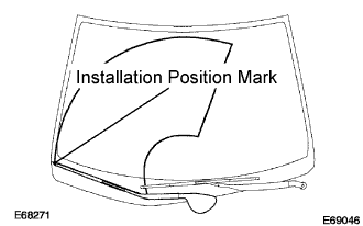 |
Install the front wiper arm and blade assembly RH with the 2 nuts at the position as shown in the illustration.
Operate the front wipers while spraying water or washer fluid on the windshield.
Make sure that the wipers function properly and there is no interference with the vehicle body.
| 100. INSTALL FRONT WHEELS |
| 101. ADD AND INSPECT HYBRID TRANSAXLE FLUID |
Fill oil.
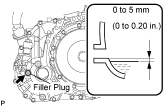 |
Check that the oil surface is within 5 mm (0.20 in.) from the lowest position of the inner surface of the differential filler plug opening.
Using a socket hexagon wrench 10 mm, temporarily tighten the filler plug and gasket.
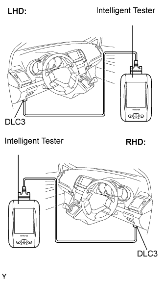 |
Connect the intelligent tester to the DLC3.
Turn the ignition switch to the ON position.
Select the inspection mode. (Click here)
On the tester, enter the following menus: Powertrain / Hybrid Control / Active test / Inspection Mod 1.
Turn the ignition switch to the ON position and turn the tester on.
Using a socket hexagon wrench 10 mm, remove the filler plug and gasket.
Fill oil.
|
Check that the oil surface is within 5 mm (0.20 in.) from the lowest position of the inner surface of the differential filler plug opening.
Check for leaks if the quantity of oil is low.
Using a socket hexagon wrench 10 mm, install the filler plug, and a new gasket.
| 102. ADD ENGINE OIL |
| 103. CHECK FOR FUEL LEAKS |
Connect the intelligent tester to the DLC3.
Turn the ignition switch to the ON position and turn the intelligent tester on.
Select the Active Test mode on the intelligent tester to operate the fuel pump.
Check that there are no fuel leaks anywhere in the fuel system after performing maintenance.
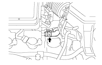
| 104. ADD COOLANT (Hybrid side) |
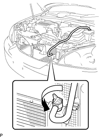 |
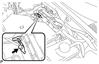
Loosen the bleeder plug shown in the illustration and connect a hose.
Add coolant from the reserve tank.
 |
Add coolant until the level of coolant in the hose attached to the bleeder plug reaches the same level as the FULL line of the reserve tank.
When using the intelligent tester:
|
Connect the intelligent tester to the DLC3.
Turn the ignition switch to the ON position.
Select the inspection mode (Click here).
On the tester, enter the following menus: Powertrain / Hybrid Control / Active test / Water Pump.
Keep the coolant at the FULL level in the reserve tank to compensate for the drop in coolant level when the air bleeds.
When not using the intelligent tester:
Put the vehicle into the READY-on state. [*1]
Turn the ignition switch off and add coolant to the FULL level because the coolant level drops as the air bleeds. [*2]
Repeat steps [*1] and [*2] until air bleeding from the coolant system is completed.
When the air is completely bled from the coolant system, tighten the plug.
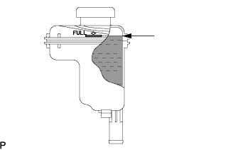 |
Add coolant to the FULL mark of the reserve tank.
| 105. ADD COOLANT (Engine side) |
Tighten the lower drain plug of the radiator.
Loosen the upper drain plug of the radiator.
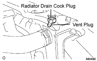 |
Install a vinyl tube to the vent plug located on the upper drain plug.
Fill the radiator with engine coolant until the vinyl tube is filled with the coolant.
Tighten the upper drain plug.
Install the radiator cap securely.
Fill the radiator reservoir tank with coolant.
Warm up the engine.
Stop the engine and wait until the coolant cools down.
Remove the radiator cap and check the coolant level inside the radiator.
If the coolant level is below the full level, perform the steps from (a) through (j) and repeat the operation until the coolant level stays the full level.
Recheck the coolant level inside the radiator reservoir tank. If it is below the full level, add the coolant.
| 106. CHECK FOR ENGINE OIL LEAKS |
| 107. CHECK FOR COOLANT LEAKS (Hybrid side) |
| 108. CHECK FOR COOLANT LEAKS (Engine side) |
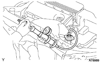 |
Fill the radiator with coolant and attach a radiator cap tester.
Warm up the engine.
Using a radiator cap tester, increase the pressure inside the radiator to 118 kPa (1.2 kgf*cm, 17 psi), and check that the pressure does not drop.
If the pressure drops, check the hoses, radiator and water pump for leaks. If no external leaks are found, check the heater core, cylinder block and cylinder head.
| 109. CHECK FOR EXHAUST GAS LEAKS |
| 110. INSPECT AND ADJUST FRONT WHEEL ALIGNMENT |
| 111. INSTALL ENGINE UNDER COVER NO.2 |
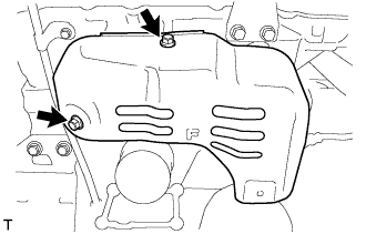
Install the 2 bolts and engine under cover No.2.
| 112. INSTALL FRONT FENDER APRON SEAL LH |
 |
Install the 2 bolts, clip and fender apron seal LH.
| 113. INSTALL FRONT FENDER APRON SEAL RH |
| 114. INSTALL FRONT FENDER SPLASH SHIELD SUB-ASSEMBLY LH |
 |
Install the fender splash shield with the screw.
| 115. INSTALL FRONT FENDER SPLASH SHIELD SUB-ASSEMBLY RH |
| 116. INSTALL ENGINE UNDER COVER NO.1 |
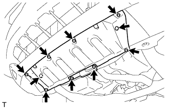 |
Install the 6 bolts, 2 screws, 2 clips and engine under cover.
| 117. INSPECT STEERING WHEEL CENTER POINT |
| 118. INSPECT IGNITION TIMING |
Set the vehicle to inspection mode (Click here).
Warm up the engine.
When using the intelligent tester:
Connect the intelligent tester (with CAN VIM) to the DLC3.
Enter DATA LIST MODE on the intelligent tester.
Check that the ignition timing advances immediately when the engine speed is increased.
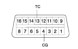 |
When not using the intelligent tester:
Using SST, connect terminals 13 (TC) and 4 (CG) of the DLC3.
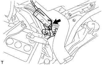 |
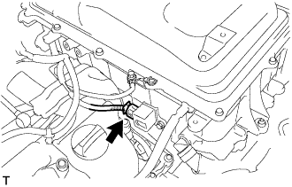
Pull out the red-colored wire harness as shown in the illustration.
Connect the tester terminal of the timing light to the engine.
Inspect ignition timing at idle.
Disconnect terminals 13 (TC) and 4 (CG) of the DLC3.
Inspect ignition timing at idle.
Confirm that the ignition timing advances when the engine rpm is increased.
Remove the timing light.
| 119. INSPECT ENGINE IDLE SPEED |
Set the vehicle to inspection mode (Click here).
Warm up the engine.
Connect the intelligent tester (with CAN VIM) to the DLC3.
Enter DATA LIST MODE on the intelligent tester.
| 120. INSPECT CO/HC |
Set the vehicle to inspection mode (Click here).
Start the engine.
Run the engine at 2,500 rpm for approximately 180 seconds.
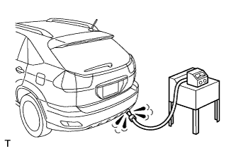 |
Insert the CO/HC meter testing probe at least 40 cm (1.3 ft) into the tailpipe during idling.
Check CO/HC concentration at idle and/or 2,500 rpm.
Check heated oxygen sensor operation (Click here).
Check heated air fuel ratio sensor operation (Click here).
See the table below for possible causes, and then inspect and repair the applicable causes if necessary.
| CO | HC | Problems | Causes |
| Normal | High | Rough idle |
|
| Low | High | Rough idle (Fluctuating HC reading) |
|
| High | High | Rough idle (Black smoke from exhaust) |
|
| 121. CHECK ABS SPEED SENSOR SIGNAL |
| 122. PERFORM INITIALIZATION |
Some system need initialization when reconnecting the battery cable. (Click here)
| 123. INSTALL ENGINE ROOM COVER SIDE |
 |
Install the 5 clips and engine room cover side
| 124. INSTALL ENGINE ROOM SIDE LH COVER |
 |
Fit the clips and install the engine room side LH cover.
