AUDIO AND VISUAL SYSTEM > TERMINALS OF ECU |
| RADIO RECEIVER |
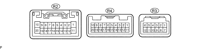
| Symbols (Terminal No.) | Wiring Color | Terminal Description | Condition | Specification |
| B (R2-1) - GND (R2-20) | L-B - BR | Battery | Always | 10 to 14 V |
| ILL+ (R2-2) - GND (R2-20) | G - BR | Illumination (rheostat) signal | Light control switch OFF → TAIL | Below 1 V → 10 to 14 V |
| ATX+ (R2-5) - GND (R2-20) | P - BR | AVC-LAN communication signal | Turn ignition switch to ACC | 2 to 3 V |
| MUTE (R2-7) - GND (R2-20) | GR - BR | MUTE signal | Audio system is playing → Changing | Above 3.5 V → Below 1 V |
| R+ (R2-8) - GND (R2-20) | B - BR | Sound signal (Right) | Audio system is playing | A waveform synchronized with sounds is output |
| L+ (R2-9) - GND (R2-20) | R - BR | Sound signal (Left) | Audio system is playing | A waveform synchronized with sounds is output |
| SLD (R2-10) - Body ground | Shielded - Body ground | Shield ground | Always | Below 1 V |
| ACC (R2-11) - GND (R2-20) | GR - BR | Accessory (ON) | Turn ignition switch to ACC | 10 to 14 V |
| ILL- (R2-12) - GND (R2-20) | W - BR | Illumination (rheostat) signal | Turn ignition switch off → ON | Below 1 V → Pulse generation |
| ANT (R2-13) - GND (R2-20) | O - BR | Power source of antenna | Radio switch ON and AM or FM | 10 to 14 V |
| ATX- (R2-15) - GND (R2-20) | L - BR | AVC-LAN communication signal | Turn ignition switch to ACC | 2 to 3 V |
| R- (R2-18) - GND (R2-20) | W - BR | Sound signal (Right) | Audio system is playing | A waveform synchronized with sounds is output |
| L- (R2-19) - GND (R2-20) | G - BR | Sound signal (Left) | Audio system is playing | A waveform synchronized with sounds is output |
| GND (R2-20) - Body ground | BR - Body ground | Ground | Always | Below 1 V |
| SWG (R4-6) - GND (R2-20) | R - BR | Steering pad switch ground | Always | Below 1 V |
| SW1 (R4-7) - GND (R2-20) | G - BR | Steering pad switch signal | Steering pad switch not operated → SEEK+ switch pushed → SEEK- switch pushed → VOL+ switch pushed → VOL- switch pushed | 4 V or more → Approx. 0.5 V → Approx. 0.9 V → Approx. 2.0 V → Approx. 3.4 V |
| SW2 (R4-8) - GND (R2-20) | V - BR | Steering pad switch signal | Steering pad switch not operated → MODE switch pushed | 4 V or more → Below 2.5 V |
| TX+ (R3-9) - GND (R2-20) | Y (*1) - BR B (*2) - BR | AVC-LAN communication signal | Turn ignition switch to ACC | 2 to 3 V |
| TX- (R3-10) - GND (R2-20) | BR (*1) - BR R (*2) - BR | AVC-LAN communication signal | Turn ignition switch to ACC | 2 to 3 V |
| STEREO COMPONENT AMPLIFIER (STANDARD SYSTEM) |
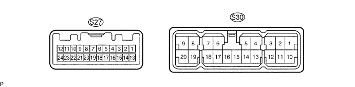
| Symbols (Terminal No.) | Wiring Color | Terminal Description | Condition | Specification |
| +B (S30-1) - GND (S30-16) | W - W-B | Battery | Always | 10 to 14 V |
| WF2+ (S30-4) - GND (S30-16) | V - W-B | Sound signal (Woofer Left) | Audio system is playing | A waveform synchronized with sounds is output |
| WF1+ (S30-5) - GND (S30-16) | P - W-B | Sound signal (Woofer Right) | Audio system is playing | A waveform synchronized with sounds is output |
| RL+ (S30-6) - GND (S30-16) | R - W-B | Sound signal (Rear Left) | Audio system is playing | A waveform synchronized with sounds is output |
| RR+ (S30-7) - GND (S30-16) | R-Y - W-B | Sound signal (Rear Right) | Audio system is playing | A waveform synchronized with sounds is output |
| FL+ (S30-8) - GND (S30-16) (*3) | Y (*1) - W-B BR (*2) - W-B | Sound signal (Front Left) | Audio system is playing | A waveform synchronized with sounds is output |
| FL+ (S30-8) - GND (S30-16) (*4) | BR - W-B | Sound signal (Front Left) | Audio system is playing | A waveform synchronized with sounds is output |
| FR+ (S30-9) - GND (S30-16) (*3) | V - W-B | Sound signal (Front Right) | Audio system is playing | A waveform synchronized with sounds is output |
| FR+ (S30-9) - GND (S30-16) (*4) | Y (*1) W-B V (*2) - W-B | Sound signal (Front Right) | Audio system is playing | A waveform synchronized with sounds is output |
| +B2 (S30-10) - GND (S30-16) | W - W-B | Battery | Always | 10 to 14 V |
| WF2- (S30-13) - GND (S30-16) | W - W-B | Sound signal (Front Left) | Audio system is playing | A waveform synchronized with sounds is output |
| WF1- (S30-14) - GND (S30-16) | L-B - W-B | Sound signal (Front Right) | Audio system is playing | A waveform synchronized with sounds is output |
| GND2 (S30-15) - Body ground | W-B - Body ground | Ground | Always | Below 1 V |
| GND (S30-16) - Body ground | W-B - Body ground | Ground | Always | Below 1 V |
| RL- (S30-17) - GND (S30-16) | GR - W-B | Sound signal (Rear Left) | Audio system is playing | A waveform synchronized with sounds is output |
| RR- (S30-18) - GND (S30-16) | L - W-B | Sound signal (Rear Right) | Audio system is playing | A waveform synchronized with sounds is output |
| FL- (S30-19) - GND (S30-16) (*3) | LG (*1) - W-B R-Y (*2) - W-B | Sound signal (Front Left) | Audio system is playing | A waveform synchronized with sounds is output |
| FL- (S30-19) - GND (S30-16) (*4) | R-Y - W-B | Sound signal (Front Left) | Audio system is playing | A waveform synchronized with sounds is output |
| FR- (S30-20) - GND (S30-16) (*3) | P - W-B | Sound signal (Front Right) | Audio system is playing | A waveform synchronized with sounds is output |
| FR- (S30-20) - GND (S30-16) (*4) | LG (*1) - W-B P (*2) - W-B | Sound signal (Front Right) | Audio system is playing | A waveform synchronized with sounds is output |
| MUTE (S27-1) - GND (S30-16) | Y - W-B | Mute signal from radio receiver | Audio system is playing → Changing | Above 3.5 V → Below 3.5 V |
| L- (S27-2) - GND (S30-16) | G - W-B | Sound signal from radio receiver (Left) | Audio system is playing | A waveform synchronized with sounds is output |
| L+ (S27-3) - GND (S30-16) | R - W-B | Sound signal from radio receiver (Left) | Audio system is playing | A waveform synchronized with sounds is output |
| R- (S27-4) - GND (S30-16) | W - W-B | Sound signal from radio receiver (Right) | Audio system is playing | A waveform synchronized with sounds is output |
| R+ (S27-5) - GND (S30-16) | B - W-B | Sound signal from radio receiver (Right) | Audio system is playing | A waveform synchronized with sounds is output |
| SLD (S27-6) - Body ground | Shield ground - Body ground | Shield ground | Always | Below 1 V |
| TX- (S27-7) - GND (S30-16) | L - W-B | AVC-LAN communication signal | Turn ignition switch to ACC | 2 to 3 V |
| TX+ (S27-8) - GND (S30-16) | P - W-B | AVC-LAN communication signal | Turn ignition switch to ACC | 2 to 3 V |
| SPD (S27-11) - GND (S30-16) | SB - W-B | Speed signal from combination meter | Vehicle is driven | Pulse generation |
| ACC (S27-12) - GND (S30-16) | P - W-B | Accessory (ON) | Turn ignition switch to ACC | Below 1 V → 10 to 14 V |
| N-MU (S27-21) - GND (S30-16) (*1) | V - W-B | Mute signal from navigation ECU | Navigation system is changing | Above 3.5 V → Below 1 V |
| STEREO COMPONENT AMPLIFIER (MARK LEVINSON SYSTEM) |
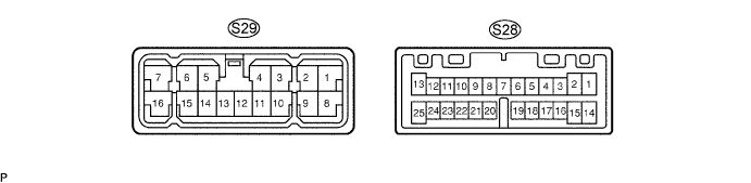
| Symbols (Terminal No.) | Wiring Color | Terminal Description | Condition | Specification |
| FR+ (S29-1) - GND (S29-13) | P - W-B | Sound signal (Front Right) | Audio system is playing | A waveform synchronized with sounds is output |
| FL+ (S29-2) - GND (S29-13) | V - W-B | Sound signal (Front Left) | Audio system is playing | A waveform synchronized with sounds is output |
| RR+ (S29-3) - GND (S29-13) | R-Y - W-B | Sound signal (Rear Right) | Audio system is playing | A waveform synchronized with sounds is output |
| RL+ (S29-4) - GND (S29-13) | R - W-B | Sound signal (Rear Left) | Audio system is playing | A waveform synchronized with sounds is output |
| CTF+ (S29-5) - GND (S29-13) | GR - W-B | Sound signal (Center) | Audio system is playing | A waveform synchronized with sounds is output |
| B+ (S29-7) - GND (S29-13) | W - W-B | Battery | Always | 10 to 14 V |
| FR- (S29-8) - GND (S29-13) | L-B - W-B | Sound signal (Front Right) | Audio system is playing | A waveform synchronized with sounds is output |
| FL- (S29-9) - GND (S29-13) | W - W-B | Sound signal (Front Left) | Audio system is playing | A waveform synchronized with sounds is output |
| RR- (S29-10) - GND (S29-13) | L - W-B | Sound signal (Rear Right) | Audio system is playing | A waveform synchronized with sounds is output |
| RL- (S29-11) - GND (S29-13) | GR - W-B | Sound signal (Rear Left) | Audio system is playing | A waveform synchronized with sounds is output |
| E (S29-12) - Body ground | W-B - Body ground | Ground | Always | Below 1 V |
| GND (S29-13) - Body ground | W-B - Body ground | Ground | Always | Below 1 V |
| CTF- (S29-14) - GND (S29-13) | B - W-B | Sound signal (Center) | Audio system is playing | A waveform synchronized with sounds is output |
| B+ (S29-16) - GND (S29-13) | W - W-B | Battery | Always | 10 to 14 V |
| TFR+ (S28-1) - GND (S29-13) (*3) | V - W-B | Sound signal (Front Right) | Audio system is playing | A waveform synchronized with sounds is output |
| TFR+ (S28-1) - GND (S29-13) (*4) | Y (*1) - W-B V (*2) - W-B | Sound signal (Front Right) | Audio system is playing | A waveform synchronized with sounds is output |
| TFL+ (S28-2) - GND (S29-13) (*3) | Y (*1) - W-B BR (*2) - W-B | Sound signal (Front Left) | Audio system is playing | A waveform synchronized with sounds is output |
| TFL+ (S28-2) - GND (S29-13) (*4) | BR - W-B | Sound signal (Front Left) | Audio system is playing | A waveform synchronized with sounds is output |
| MTX+ (S28-5) - GND (S29-13) | P - W-B | AVC-LAN communication signal | Turn ignition switch to ACC | 2 to 3 V |
| N-MU (S28-9) - GND (S29-13) | V (*1) - W-B | Mute signal from navigation ECU | Audio system is playing → Changing | Above 3.5 V → Below 1 V |
| R+ (S28-11) - GND (S29-13) | B - W-B | Sound signal from radio receiver (Right) | Audio system is playing | A waveform synchronized with sounds is output |
| L+ (S28-12) - GND (S29-13) | R - W-B | Sound signal from radio receiver (Left) | Audio system is playing | A waveform synchronized with sounds is output |
| SPD (S28-13) - GND (S29-13) | SB - W-B | Speed signal from combination meter | Vehicle is driven | Pulse generation |
| TFR- (S28-14) - GND (S29-13) (*3) | P - W-B | Sound signal (Front Right) | Audio system is playing | A waveform synchronized with sounds is output |
| TFR- (S28-14) - GND (S29-13) (*4) | LG (*1) - W-B P (*2) - W-B | Sound signal (Front Right) | Audio system is playing | A waveform synchronized with sounds is output |
| TFL- (S28-15) - GND (S29-13) (*3) | LG (*1) - W-B R-Y (*2) - W-B | Sound signal (Front Left) | Audio system is playing | A waveform synchronized with sounds is output |
| TFL- (S28-15) - GND (S29-13) (*4) | R-Y - W-B | Sound signal (Front Left) | Audio system is playing | A waveform synchronized with sounds is output |
| MTX- (S28-18) - GND (S29-13) | L - W-B | AVC-LAN communication signal | Turn ignition switch to ACC | 2 to 3 V |
| ACC (S28-20) - GND (S29-13) | P - W-B | Accessory (ON) | Turn ignition switch off → ACC or ON | 10 to 14 V |
| MUTE (S28-21) - GND (S29-13) | GR (*3) - W-B Y (*4) - W-B | Mute signal from radio receiver | Audio system is playing → Changing | Above 3.5 V → Below 1 V |
| SGND (S28-22) - Body ground | Shield ground - Body ground | Shield ground | Always | Below 1 V |
| R- (S28-23) - GND (S29-13) | W - W-B | Sound signal from radio receiver (Right) | Audio system is playing | A waveform synchronized with sounds is output |
| L- (S28-24) - GND (S29-13) | G - W-B | Sound signal from radio receiver (Left) | Audio system is playing | A waveform synchronized with sounds is output |
| GATEWAY ECU (Click here) |
