AUDIO AND VISUAL SYSTEM > Radio Receiver Power Source Circuit |
| 1.INSPECT RADIO RECEIVER |
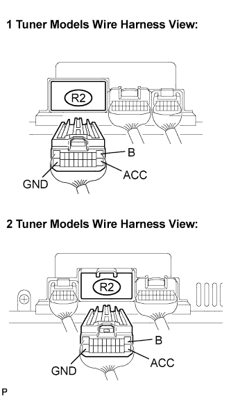 |
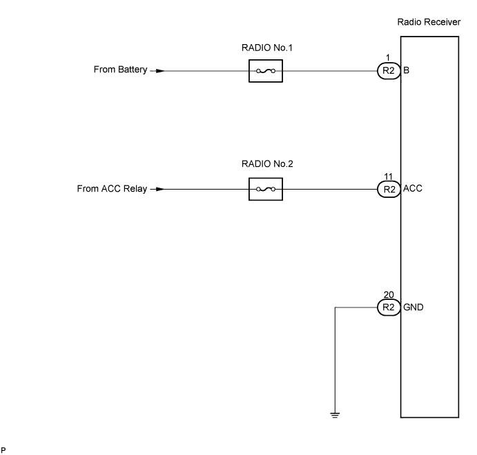
Disconnect the radio receiver R2 connector.
Measure the resistance according to the value in the table below.
| Tester connection | Condition | Specified condition |
| GND - Body ground | Always | Below 1 Ω |
Measure the voltage according to the values in the table below.
| Tester connection | Condition | Specified condition |
| B - GND | Always | 10 to 14 V |
| ACC - GND | Ignition SW ACC | 10 to 14 V |
|
| ||||
| OK | ||
| ||
