AUDIO AND VISUAL SYSTEM > Steering Pad Switch Circuit |
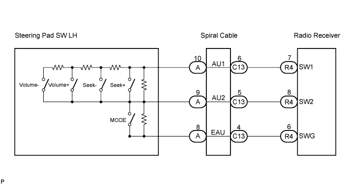
| 1.INSPECT RADIO RECEIVER |
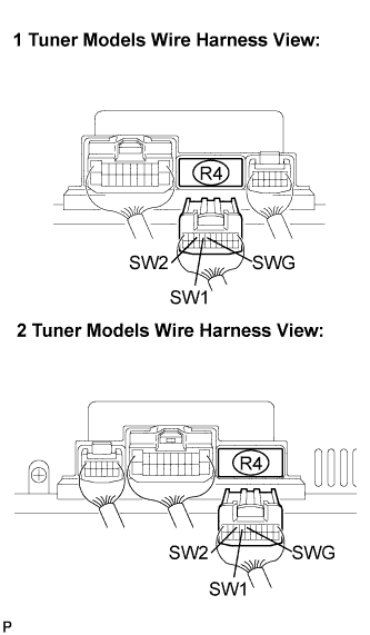 |
Disconnect the radio receiver connector R4.
Measure the resistance according to the value(s) in the table below.
| Tester connection | Condition | Specified condition |
| SW1 - SWG | No switch is pushed | Approx. 100 kΩ |
| SW1 - SWG | SEEK+ switch: push | Approx. 0 Ω |
| SW1 - SWG | SEEK- switch: push | Approx. 0.3 kΩ |
| SW1 - SWG | VOL+ switch: push | Approx. 1 kΩ |
| SW1 - SWG | VOL- switch: push | Approx. 3.2 kΩ |
| SW2 - SWG | No switch is pushed | Approx. 100 kΩ |
| SW2 - SWG | MODE switch: push | Approx. 0 Ω |
|
| ||||
| OK | ||
| ||
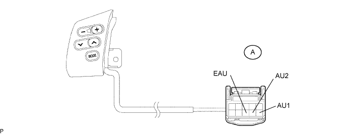
| 2.INSPECT STEERING PAD SWITCH LH |
Disconnect the steering pad switch LH connector.
Measure the resistance according to the values in the table below.
| Tester connection | Condition | Specified condition |
| AU1 - EAU | No switch is pushed | Approx. 100 kΩ |
| AU1 - EAU | SEEK+ switch: push | Approx. 0 Ω |
| AU1 - EAU | SEEK- switch: push | Approx. 0.3 kΩ |
| AU1 - EAU | VOL+ switch: push | Approx. 1 kΩ |
| AU1 - EAU | VOL- switch: push | Approx. 3.2 kΩ |
| AU2 - EAU | No switch is pushed | Approx. 100 kΩ |
| AU2 - EAU | MODE switch: push | Approx. 0 Ω |
|
| ||||
| OK | |
| 3.INSPECT SPIRAL CABLE |
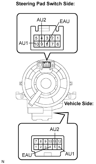 |
Disconnect the steering pad switch and spiral cable connectors.
Measure the resistance according to the value(s) in the table below.
| Tester connection | Condition | Specified condition |
| EAU - EAU | Always | Below 1 Ω |
| AU1 - AU1 | Always | Below 1 Ω |
| AU2 - AU2 | Always | Below 1 Ω |
|
| ||||
| NG | ||
| ||
